Lubricant material for assisting machining process and machining method

a technology of lubricant material and machining method, which is applied in the direction of film/foil adhesive, turning machine accessories, synthetic resin layered products, etc., can solve the problems of reducing the quality of processed holes, reducing the life of drills, and non-uniform inside diameter, so as to reduce the load of machining tools and reduce the occurrence of chipping

Active Publication Date: 2019-08-20
MITSUBISHI GAS CHEM CO INC
View PDF21 Cites 3 Cited by
  • Summary
  • Abstract
  • Description
  • Claims
  • Application Information

AI Technical Summary

Benefits of technology

[0009]Machining process of fiber reinforced composite materials, is typically performed using a drill. In the general drilling with a drill, the drill has an exceedingly short lifespan, and the drill bit suffers abrasion with increase in the number of processed holes, resulting in reduction in the quality of processed holes. Specifically, the processed holes are more likely to have a small inside diameter, and the splintering of carbon fiber (which is a phenomenon in which a part of fiber constituting a fiber reinforced composite material remains as burrs around processed holes without being cut off) occurs easily at the exit portion of drill penetration. Furthermore, peeling between layers of prepregs constituting a fiber reinforced composite material (hereinafter, referred to as “delamination”) also occurs easily. In addition, each processed hole has a nonuniform inside diameter due to the abrasion of a drill bit, and delamination may occur from the irregularity of the processed hole. Such a phenomenon is accepted as a serious defect. As mentioned above, the abrasion of a drill bit is likely to cause problems associated with the quality of processed holes. Meanwhile, for example, the production of structures using CFRP for aircrafts particularly requires high quality machining process. Thus, it is very important to solve the problems described above, such as splintering and delamination.
[0010]In the machining work of CFRP, the problems associated with the quality of processed holes arise more easily as the abrasion of a machining tool proceeds with machining resistance increased. Particularly, for example, high strength CFRP intended for aircrafts contains carbon fiber at a high density. Therefore, the frequency of rubbing of carbon fiber by a drill is increased so that the abrasion of the machining tool proceeds more rapidly. As measures against this, the tool is changed at shorter intervals in order to maintain hole quality. Under present circumstances, the ratio of tooling cost to processing cost is high.

Problems solved by technology

In the general drilling with a drill, the drill has an exceedingly short lifespan, and the drill bit suffers abrasion with increase in the number of processed holes, resulting in reduction in the quality of processed holes.
In addition, each processed hole has a nonuniform inside diameter due to the abrasion of a drill bit, and delamination may occur from the irregularity of the processed hole.
As mentioned above, the abrasion of a drill bit is likely to cause problems associated with the quality of processed holes.
In the machining work of CFRP, the problems associated with the quality of processed holes arise more easily as the abrasion of a machining tool proceeds with machining resistance increased.
Under present circumstances, the ratio of tooling cost to processing cost is high.
In this respect, as described in Patent Literature 1, improvement in the workability of fiber reinforced composite materials (e.g., CFRP), for which machining process is difficult, has been studied in terms of tools, but has produced insufficient effects.
Even if a drill dedicated to metals is used, the drill has a short lifespan.
In the case of using a general drill, the drill has an exceedingly short lifespan.
Furthermore, the drill bit suffers abrasion with increase in the number of processed holes, resulting in reduction in the quality of processed holes.
In addition, the abrasion of the drill may create the space between a metal material and another structural material (e.g., CFRP) to be bolted.
Thus, uplift may arise between these structural materials, or scraps may enter the created space.
As mentioned above, the abrasion of a drill bit is likely to cause problems associated with the quality of processed holes.

Method used


Image

  • Lubricant material for assisting machining process and machining method
  • Lubricant material for assisting machining process and machining method
  • Lubricant material for assisting machining process and machining method

Examples


embodiment 1

[0177]When the machining step is a step of forming a machined portion (e.g., a processed hole) having the exit and the entrance of the machining tool, the machining method of embodiment 1 comprises, before the machining step, a close contact step of closely bringing in advance the lubricant material for assisting machining process into contact with a portion to be the exit and / or a portion to be the entry of the machining tool, in the workpiece material. In this context, the “portion to be the exit” can be used interchangeably with a face to serve as the exit if this portion is a face. In response to this, the “portion to be the entry” can be used interchangeably with a face to serve as the entrance.

[0178]In drilling work, the neighborhoods of the edges of a hole (machined portion) to be obtained correspond to the “portion to be the entry” and the “portion to be the exit”. In grooving work, the neighborhood of the edge of a groove (machined portion) to be obtained corresponds to the...

embodiment 1-1

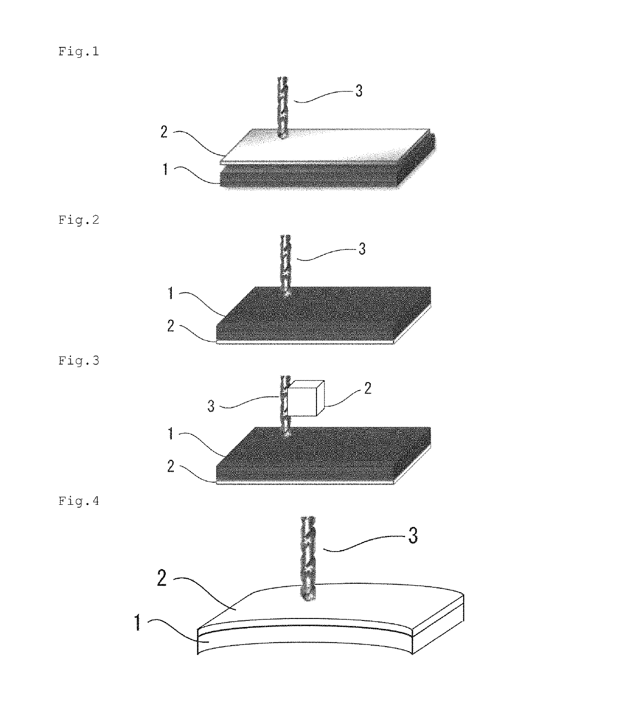
[0180]In embodiment 1-1, the lubricant material for assisting machining process 2 is closely brought in advance into contact with a portion to be the entry of a machining tool 3, in the workpiece material 1, and the workpiece material 1 is processed with the machining tool 3 (FIG. 1). In this case, the lubricant material for assisting machining process 2 comes in contact with the machining tool 3 prior to the workpiece material 1.

[0181]The lubricant material for assisting machining process is placed, for use, at the portion to be the entry of the machining tool to thereby transfer a lubricating component of the lubricant material for assisting machining process to the tip of the tool immediately before processing. Therefore, the lubricating effect of the lubricant material for assisting machining process is exerted more effectively. The lubricant material for assisting machining process placed at the portion to be the entry also acts as a buffer material upon entry of the machining ...

embodiment 1-2

[0187]In embodiment 1-2, the lubricant material for assisting machining process 2 is closely brought in advance into contact with a portion to be the exit of the machining tool 3, in the workpiece material 1, and the workpiece material 1 is processed with the machining tool 3 (FIG. 2). In this case, the lubricant material for assisting machining process 2 comes in contact with the machining tool 3 after the completion of penetration into the workpiece material 1.

[0188]The lubricant material for assisting machining process is placed, for use, at the portion to be the exit of the machining tool so that the lubricant material for assisting machining process acts as a lubricant agent. This can reduce load to the machining tool at the time of machining process, suppress the abrasion of the machining tool, and prolong the lifespan of the machining tool. As a result, cost required for machining tools, the number of runs of a machining tool change step, or the like can be reduced. Thus, mac...


PUM

PropertyMeasurementUnit
particle sizeaaaaaaaaaa
thicknessaaaaaaaaaa
thicknessaaaaaaaaaa

Abstract

The present invention provides a lubricant material for assisting machining process comprising a high molecular weight compound (A) having a weight average molecular weight of 5×10⁴ or higher and 1×10⁶ or lower, a medium molecular weight compound (B) having a weight average molecular weight of 1×10³ or higher and lower than 5×10⁴, and a carbon (C) having an average particle size of 100 μm or larger.

Description

CROSS-REFERENCE TO RELATED APPLICATIONS[0001]This application is a U.S. national phase application filed under 35 U.S.C. § 371 of International Application PCT / JP2016 / 072929, filed on Aug. 4, 2016, designating the United States, which claims priority from Japanese Application Number 2015-156386, filed Aug. 6, 2015; Japanese Application Number 2015-217797, filed Nov. 5, 2015; Japanese Application Number 2015-217799, filed Nov. 5, 2015; Japanese Application Number 2015-219830, filed Nov. 9, 2015; Japanese Application Number 2015-219832, filed Nov. 9, 2015; Japanese Application Number 2015-221629, filed Nov. 11, 2015; Japanese Application Number 2015-221630, filed Nov. 11, 2015; Japanese Application Number 2015-221031, filed Nov. 11, 2015; and Japanese Application Number 2015-221032, filed Nov. 11, 2015.FIELD OF THE INVENTION[0002]The present invention relates to a lubricant material for assisting machining process and a machining method.BACKGROUND OF THE INVENTION[0003]Fiber reinforce...

Claims


Application Information

Patent Timeline
Patent Type & Authority Patents(United States)
IPC IPC(8): B23Q11/10C10M125/02C09J7/20C09J201/00C10M111/04C10M107/32C10M107/28C10M107/26C10M107/24C10M107/12B23B35/00C10M107/42C10M107/38C10M107/36C10M107/34C10M107/00C10M103/02C10M107/44C09J7/22C10N20/04C10N20/06C10N30/16C10N30/18C10N40/20
CPCB23Q11/1046B23Q11/10C09J7/20C09J201/00C10M107/12C10M107/24C10M107/26C10M107/28C10M107/32C10M111/04C10M125/02B23B35/00C10N2040/20C10M103/02C10M107/00C10M107/34C10M107/36C10M107/38C10M107/42C10M107/44C10M2201/041C10N2020/04C10N2020/06C10N2030/16C10N2030/18B23Q11/00C08K3/04C09J7/22C09J2301/408C09J2433/00C10N2020/02C10M2209/103C10N2020/091C10N2020/093C10M2209/084C10M2209/102C10N2030/06C10N2030/76C10N2040/22C10M2209/04C10M2209/12C10M2217/044C10M2217/045C10M2213/04C10M2217/028C10M2205/04C10M171/04C10M171/06B23B2226/275B23B2222/88B23B2250/12C10M2209/109C10M2209/108C10M107/22C10M107/40B32B27/08
Inventor MATSUYAMA, YOUSUKEOGASHIWA, TAKAAKI
Owner MITSUBISHI GAS CHEM CO INC
Why Eureka
Try Eureka