Automatic speed reducing ratio-switching apparatus

a technology of automatic speed reduction and ratio switching, which is applied in the direction of fluid gearing, gearing details, gearing, etc., can solve the problems of deteriorating response speed (response speed) of internal gears, weakened force (thrust force) that displace internal gears in the axial direction, etc., and achieves convenient and optimal production of speed reducing ratio switching

Inactive Publication Date: 2009-03-31
SMC CORP
View PDF23 Cites 2 Cited by
  • Summary
  • Abstract
  • Description
  • Claims
  • Application Information

AI Technical Summary

Benefits of technology

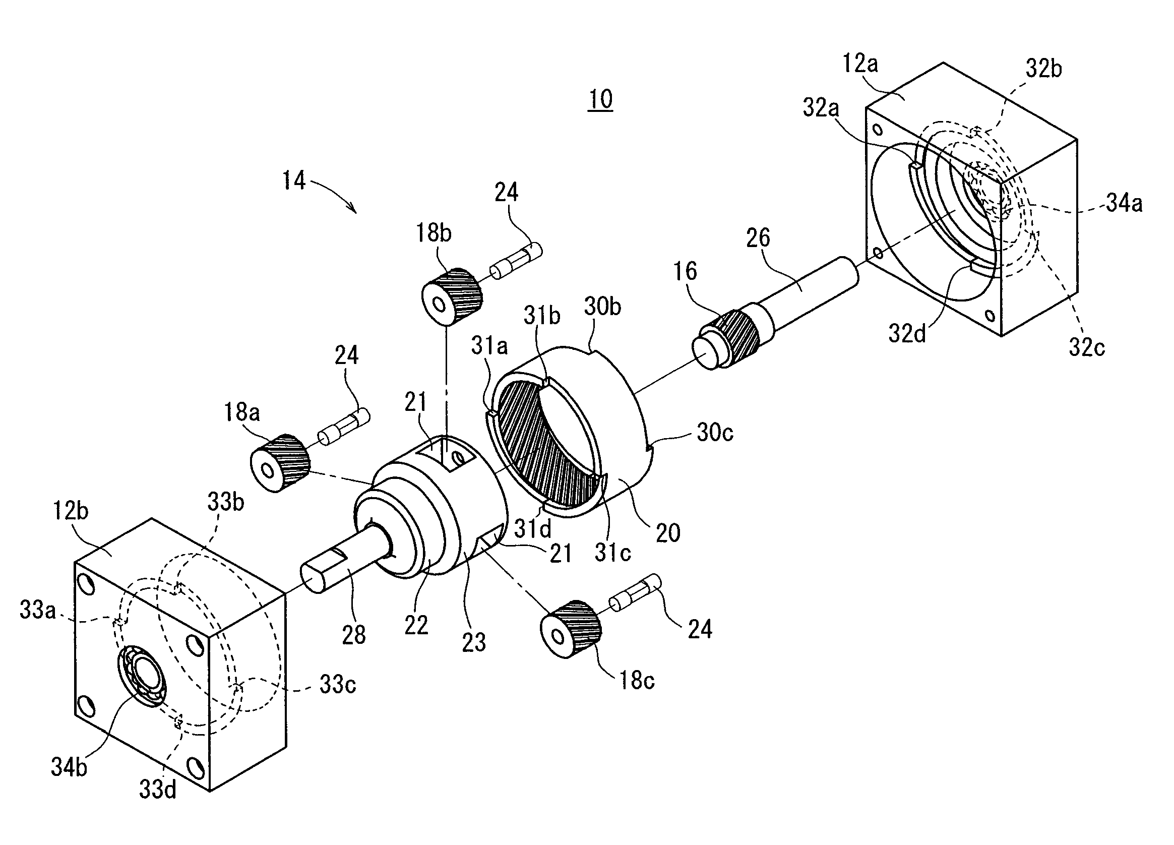
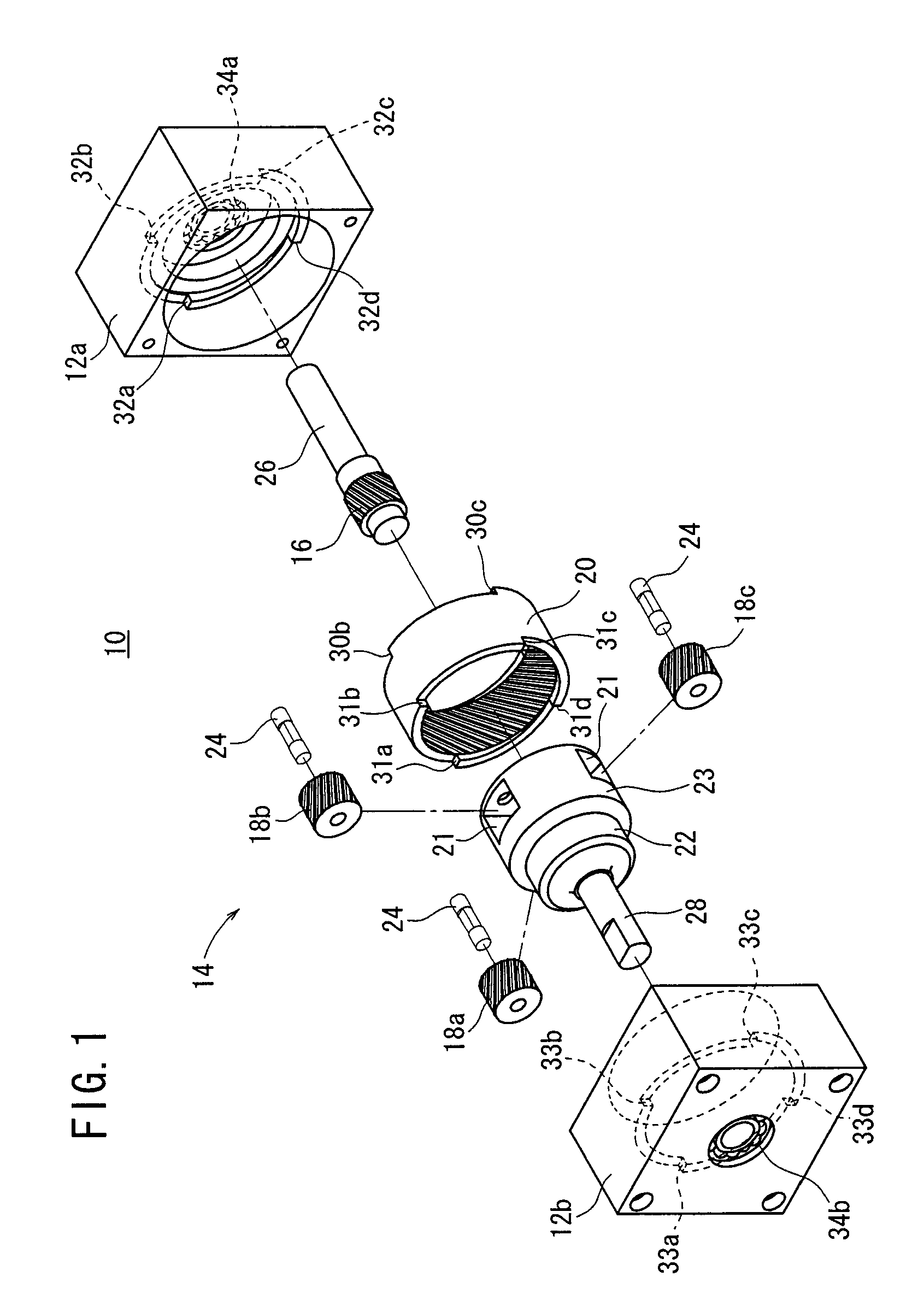
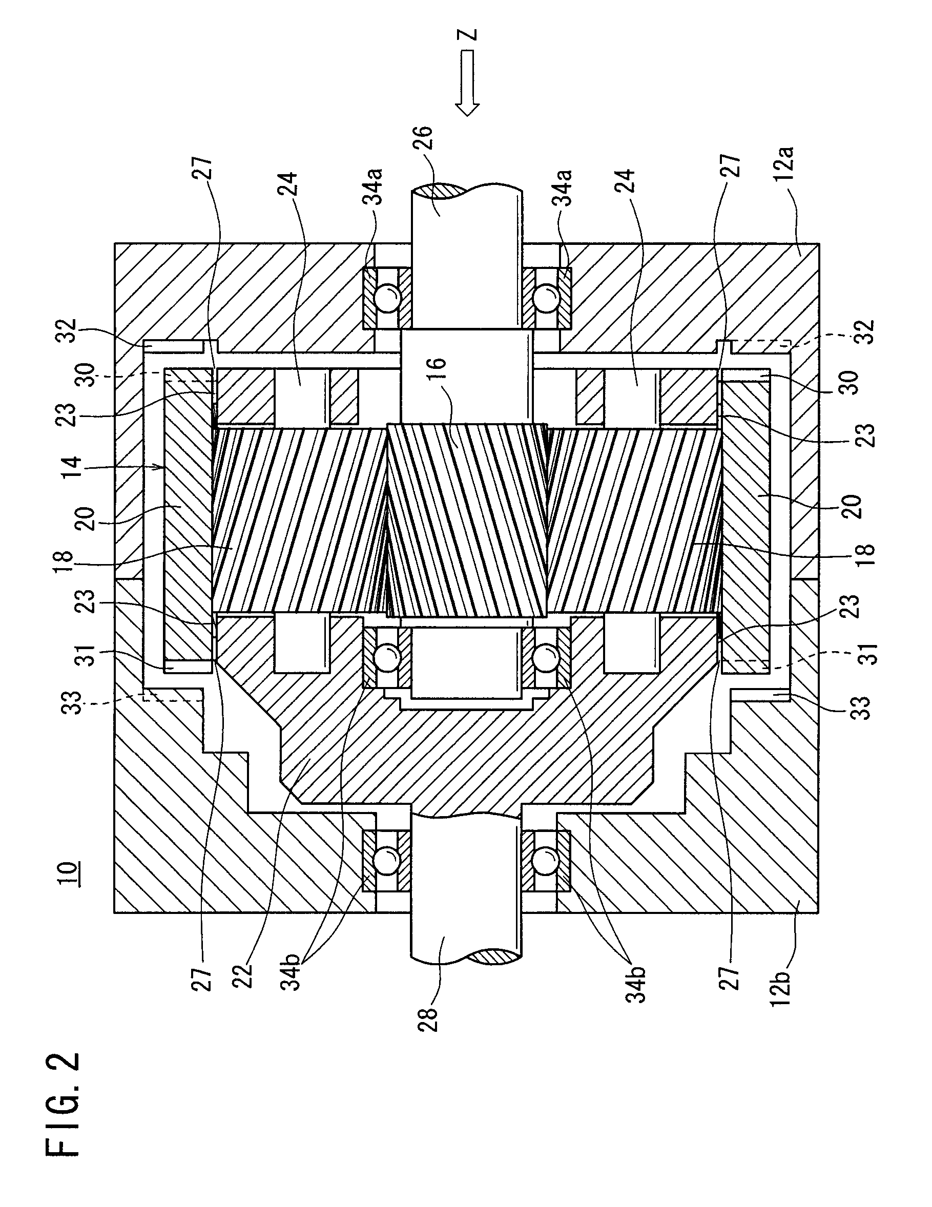
[0009]A general object of the present invention is to provide an automatic speed reducing ratio-switching apparatus, which can be produced conveniently and optimally by persons skilled in the art, by setting, for example, various items such as gears or the like as constitutive parts, and establishing relationships between such constitutive parts.
[0013]According to the present invention, a rising angle γ of a pawl is set to satisfy a relational expression in which 0≦tan γ<(η·di) / {dp ·tan(90−α)}. Accordingly, the height 10 of the pawl can be set appropriately, whereby excessive abrasion of the pawl and breakage of the root portion of the pawl can be avoided.
[0015]Further, according to the present invention, when lock sections abut against lock receiving sections of the internal gear, a cylindrical member, which includes such lock sections, is rotated between a first bearing and a second bearing. Accordingly, an impact exerted upon abutment thereof can be buffered, making it possible to suppress abutment sounds as thoroughly as possible.
[0016]Moreover, according to the present invention, various items such as gears or the like, which make up constitutive parts of the apparatus, and the relationships between such constitutive parts, are established as described above. Accordingly, the apparatus can be produced conveniently and optimally by persons skilled in the art.

Problems solved by technology

On the other hand, if the helix angle θ of the helical gear is set so as to be less than 25 degrees, then a force (thrust force) that acts to displace the internal gear in the axial direction is weakened, and response sensitivity (response speed) of the internal gear is deteriorated.

Method used


Image

  • Automatic speed reducing ratio-switching apparatus
  • Automatic speed reducing ratio-switching apparatus
  • Automatic speed reducing ratio-switching apparatus

Examples


first modified embodiment

[0170]As shown in FIGS. 24 and 25, a carrier 400 includes a plurality of (for example, three stripes of) grooves 402 formed on an outer diameter surface of the inner section 223, which are parallel to the axial direction.

second modified embodiment

[0171]As shown in FIG. 26, a carrier 410 includes a plurality of annular grooves 412 formed on an outer diameter surface of the inner section 223, which are parallel to the circumferential direction and perpendicular to the axial direction.

third modified embodiment

[0172]As shown in FIG. 27, a carrier 420 includes a plurality of inclined grooves 422 formed on an outer diameter surface of the inner section 223, which intersect the axial direction at a predetermined angle.


PUM


Abstract

Helical gears, which are provided for a sun gear, planet gears, and an internal gear, have helix angles θ of not less than 25 degrees and not more than 45 degrees. Pawls provided for lock sections and internal gear lock receiving sections of the internal gear have rising angles γ, respectively, that satisfy the relational expression, 0 ≦tan γ<(η·di) / {dp·tan(90−α)}, wherein α is the helix angle of the sun gear, η is the screw efficiency of the sun gear as a sliding screw, dp is the pitch circle diameter of the sun gear, and di is an outer diameter of the internal gear defining a center of application of torque of the pawls.

Description

BACKGROUND OF THE INVENTION[0001]1. Field of the Invention[0002]The present invention relates to an automatic speed reducing ratio-switching apparatus, which is capable of automatically switching a speed-reducing ratio transmitted from an output shaft, for example, to another member or an apparatus using a planetary gear mechanism when an applied load exceeds a predetermined torque. As described later, the present invention can be applied and utilized extensively in a variety of different fields.[0003]2. Description of the Related Art[0004]A speed reducing ratio-switching mechanism has been hitherto applied, for example, to machine systems such as construction machines. In such machine systems, an electric cylinder is used as an actuator in an expansion / contraction operation system for driving a link mechanism.[0005]In such an electric cylinder, a rotary shaft is connected to an input portion of an electric motor in a casing, and a screw shaft is arranged within the rotary shaft. Th...

Claims


Application Information

Patent Timeline
Patent Type & Authority Patents(United States)
IPC IPC(8): F16H47/08F16H3/62F16H57/02F16H57/028F16H57/029F16H57/03F16H57/08
CPCF16H3/54F16H61/0295F16H3/44F16H3/00F16H1/28
Inventor NAGAI, SHIGEKAZUSAITOH, AKIOMASUI, RYUICHIIMAMURA, MASAKI
Owner SMC CORP
Why Eureka
Try Eureka