Brake system with electromotively driven piston/cylinder system

a technology of electromotive driving and brake system, which is applied in the direction of brake action initiation, braking system, coupling, etc., can solve the problems of system not establishing itself, weak vacuum, and construction implementation of wedge brake, and require additional rollers

Active Publication Date: 2013-02-12
IPGATE
View PDF21 Cites 11 Cited by
  • Summary
  • Abstract
  • Description
  • Claims
  • Application Information

AI Technical Summary

Benefits of technology

[0011]The brake system according to the invention is advantageously characterised in that it implements power-assisted braking and the servo device in the smallest space per brake circuit by means of just one piston-cylinder unit. The piston-cylinder unit is also used for building up and reducing the brake pressure, to implement the ABS and antislip regulation and in the case of failure of the energy supply or malfunctioning of the drive device. A small, integrated and inexpensive modular unit is thus advantageously produced for power-assisted braking (PAB) and regulation, whereby this is accompanied by a reduction in installation space, assembly costs and additional hydraulic and vacuum connecting lines. Moreover, owing to the short overall length, the spring dome for example advantageously does not act on the master cylinder and the crank gear in the event of a front impact.
[0012]The advantageous provision of sensor system and a travel simulator means that a variable pedal characteristic, such as a brake-by-wire function, i.e. increase in brake pressure, can be freely variably adjusted independently of pedal actuation, even when the braking effect of the generator is taken into account in the case of recuperable brakes.
[0013]Furthermore with an appropriate configuration there is no disadvantageous failure of the brake pedal if the drive fails since the pedal acts directly on the piston of the system. Lower pedal forces also advantageously result hereby in the case of failure of the energy supply since the pistons have a smaller effective area than conventional master cylinders. This is possible by separating the piston travel in the case of faultless and failed boosting. This is called a gear jump which reduces the pedal force for the same braking effect by up to 40%. Reducing the overall complexity, including that of the electrical connections, advantageously results in a reduction in the failure rate moreover.
[0014]An improvement in the ABS / ESP regulation by finely regulated pressure control with variable pressure increase and, in particular pressure reduction, speeds can also be achieved by the electromotive drive. A pressure reduction to below 1 bar in the region of a vacuum is also possible for operation with the smallest coefficients of friction, for example wet ice. A rapid increase in pressure at the start of braking, for example 0 to 100 bar, can also be achieved in less than 50 ms, and this results in a considerable reduction in braking distance.

Problems solved by technology

In the case of spark ignition engines the internal-combustion engine is used as the energy source but as a direct injection engine still only supplies a weak vacuum, in particular at the higher level.
Except for use in armoured vehicles, these systems did not establish themselves for cost reasons.
The constructional implementation of the wedge brake, which requires additional rollers for hysteresis reasons, which in turn require integration in the calliper, has not yet been achieved.
The pressure reduction speed is still not optimal since it is highly non-linear.
The pressure reduction speed is also determined by the relatively low pumping level in the case of a μ-jump or with a low coefficient of friction, and this leads to large deviations and results therewith in a braking distance loss.

Method used


Image

  • Brake system with electromotively driven piston/cylinder system
  • Brake system with electromotively driven piston/cylinder system
  • Brake system with electromotively driven piston/cylinder system

Examples


Embodiment Construction

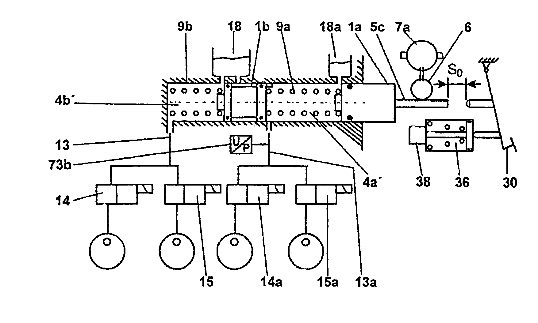
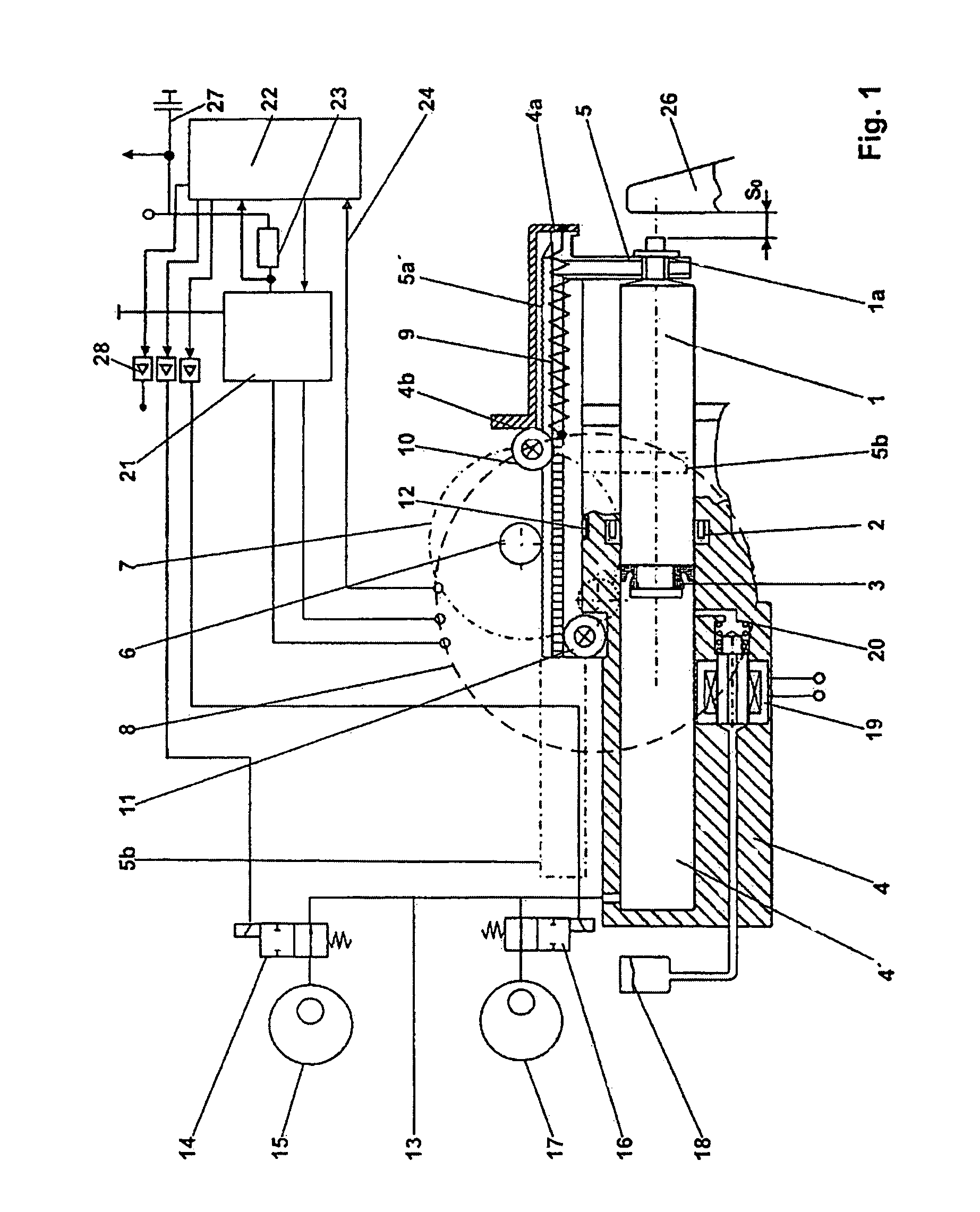
[0029]FIG. 1 shows a detail of the integrated unit which is responsible for generating pressure or power-assisted braking. In this connection the piston 1 with the conventional seals 2 and 3 is moved in the cylinder housing 4 parallel to the piston via a specially designed toothed rack 5a. The seal 2 is designed in such a way that it also provides a seal in the case of a vacuum in the piston chamber 4′. This toothed rack 5a transmits the force to the leading, crowned end of the piston 1. At this location it has a collar stud 1a via which the toothed rack 5a, with restoring spring 9, brings the piston into the starting position. In this case the toothed rack adjoins the cylinder housing 4a. This external spring has the advantage that the cylinder has a short design and little clearance volume, and this is advantageous for ventilation. Owing to the lateral forces the toothed rack is mounted in the rollers 10 and 11 with a slider 12. FIG. 1 clearly shows that the parallel arrangement o...


PUM


Abstract

The invention relates to a brake system which comprises an actuating device (26), especially a brake pedal (30), and a control / regulation device (22). Said control / regulation device (22) controls an electromotive drive device (8) in response to the movement and / or position (38) of the actuating device (30). The drive device (8) adjusts a piston (1) of a piston / cylinder system via a non-hydraulic transmission device (6), thereby adjusting a pressure in the working compartment (4′) of the cylinder (4). Said working compartment (4′) is connected to a wheel brake (15, 17) via a pressure conduit (13). In case of drive device (8) failure, the actuating device (26) adjusts the piston (1) or the drive device (8).

Description

[0001]The present invention relates to a brake system, comprising an actuating device, in particular a brake pedal, and a control and regulating device, the control and regulating device controlling an electromotive drive device using the movement and / or position of the actuating device, the drive device adjusting a piston of a piston-cylinder system via a non-hydraulic gearing device, so a pressure is adjusted in the working chamber of the cylinder, the working chamber being connected to a wheel brake by a pressure line.PRIOR ART[0002]Modern brake systems comprise power-assisted braking, i.e. conversion of the pedal force into a correspondingly boosted braking torque at the wheel brakes and braking force regulation by way of open or closed regulating and control circuits. Except for in a few cases in the automobile sector the hydraulic line is used as the transmitting means to generate the braking pressure from the pedal force.[0003]A division into modular units between power-assis...

Claims


Application Information

Patent Timeline
Patent Type & Authority Patents(United States)
IPC IPC(8): B60T8/34
CPCB60T7/042B60T8/266B60T8/268B60T8/4077B60T8/44B60T13/745
Inventor LEIBER, HEINZLEIBER, THOMAS
Owner IPGATE
Why Eureka
Try Eureka