Control valve, electronically controllable brake system and method for controlling the electronically controllable brake system

A technology for controlling valves and control chambers, applied in brake control systems, control valves, air release valves, brakes, etc., can solve the problems of high cost and high technical cost

Active Publication Date: 2020-03-24
WABCO EURO BVBA SPRL
View PDF8 Cites 4 Cited by
  • Summary
  • Abstract
  • Description
  • Claims
  • Application Information

AI Technical Summary

Problems solved by technology

On the one hand, these pressure modulators are technically expensive to construct and, o

Method used


Image

  • Control valve, electronically controllable brake system and method for controlling the electronically controllable brake system
  • Control valve, electronically controllable brake system and method for controlling the electronically controllable brake system
  • Control valve, electronically controllable brake system and method for controlling the electronically controllable brake system

Examples


Embodiment Construction

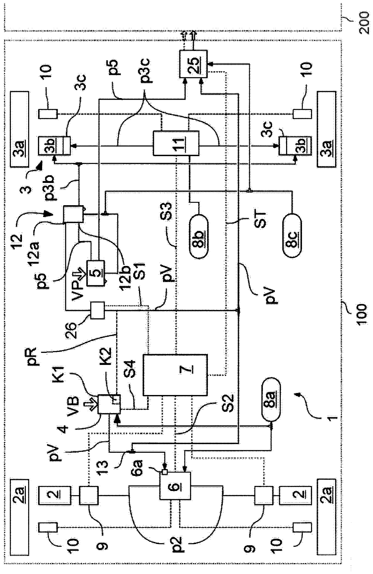
[0051] according to figure 1 A train consisting of a towing vehicle 100 and a trailer 200 hitched thereto is shown. The towing vehicle 100 has an at least partially electronically controllable dual-circuit braking system 1 , the wheel brakes 2 , 3 of the front and rear axles of which can be activated manually via the service brake valve 4 and the parking brake valve 5 . Operate to operate.

[0052] When the service brake valve 4 is actuated with a specific service brake pre-determined parameter VB, a front-axle brake pressure corresponding to this pre-determined parameter can be built up at the front axle wheel brake 2 in an electrically or pneumatically controlled manner. p2. For this purpose, the service brake control pressure pV of the front axle is transferred from the pneumatic part of the service brake valve 4 to the front axle pressure regulation module via the pneumatic redundant connection 6a, depending on the magnitude of the service brake presetting parameter VB ...


PUM


Abstract

The invention relates to a control valve, an electronically controllable brake system and a method for controlling the electronically controllable brake system. The control valve for applying a spring-loaded brake pressure to spring-loaded parts of a rear-axle wheel brake is pneumatically activated as a function of a parking-brake braking demand and a service-brake braking demand. A first controlchamber is connected via a first control piston to a control arrangement in the control valve. During an adjustment of the first control chamber via the service-brake control pressure, the spring-loaded brake pressure at the working output is a function of the service-brake control pressure or of the parking-brake control pressure. The first control piston is connected to a third control chamber,wherein the pressure in the first control chamber acts on the first control piston in one direction, and the pressure in the third control chamber acts on the first control piston in the opposite direction. The first control chamber is selectively connectable to the third control chamber via a switchable bypass valve.

Description

technical field [0001] The invention relates to a control valve for regulating the brake pressure of a spring accumulator according to the preamble of claim 1, an electronically controllable brake system with such a control valve and a system for A method of controlling the electronically controllable braking system. Background technique [0002] Conventional electronically controllable braking systems have pressure modulators assigned to the individual axles, which are electrically actuated during normal operation in order to apply specific service brake presetting parameters to the service brakes on each wheel in the circuit. In this case, the electrical control takes place starting from a central module, which actuates the respective pressure modulator via control signals as a function of the service brake braking presets. [0003] In the event of electrical failure or failure of the electric drive, the pressure modulator is traditionally provided with pneumatic redunda...

Claims


Application Information

Patent Timeline
IPC IPC(8): B60T15/04
CPCB60T15/04B60T7/20B60T8/327B60T13/662B60T13/683B60T15/041B60T15/20B60T2270/402B60T2270/414B60T13/385B60T13/588B60T13/741B60T15/027B60T2270/413F16K31/42
Inventor 保利娜·昆采维奇亚当·朗戈托马斯·穆勒莱谢克·托马
Owner WABCO EURO BVBA SPRL
Why Eureka
Try Eureka