Hydraulic brake system

A braking equipment and hydraulic technology, applied in the direction of brakes, etc., can solve problems such as the complex structure of braking equipment

Inactive Publication Date: 2011-04-20
ROBERT BOSCH GMBH
View PDF9 Cites 4 Cited by
  • Summary
  • Abstract
  • Description
  • Claims
  • Application Information

AI Technical Summary

Problems solved by technology

The disadvantage of this solution is that the brake system has a very complex structure, since the hydraulic manifold and the booster brake require a pressure medium supply in the form of a hydraulic pump and a hydraulic accumulator, respectively

Method used


Image

  • Hydraulic brake system
  • Hydraulic brake system
  • Hydraulic brake system

Examples


Embodiment Construction

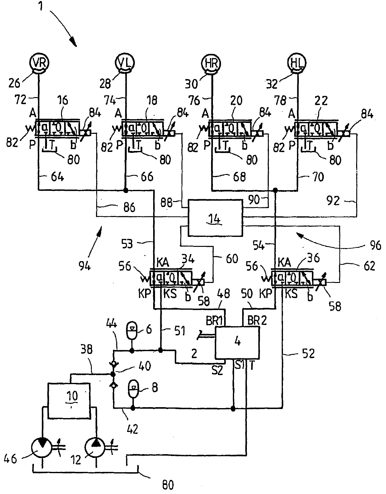
[0041] figure 1 A circuit diagram of a hydraulic braking system 1 according to a first exemplary embodiment is shown, such as for fast-moving tractors, dump trucks, municipal vehicles, for implementing ABS, ASR and / or ESP regulation. The brake device 1 mainly has a brake valve 4 manually operated by means of a brake pedal 2, two hydraulic accumulators 6, 8, an energy storage booster valve 10, a pump 12, an electronic control unit (ECU) 14, four Wheel valves 16, 18, 20, 22 and two circuit valves 34, 36, wherein the wheel brake cylinders 26, 28, 30, 32 can be loaded with braking force through the four wheel valves 16, 18, 20, 22 respectively dynamic pressure, and wherein the wheel valves 16 , 18 , 20 , 22 can be supplied with pressure medium via the two circuit valves 34 , 36 independently of the brake valve 4 . The two wheel brake cylinders 26 , 28 are assigned to the wheels (VR, VL) of the front axle and the other two wheel brake cylinders 30 , 32 are assigned to the wheels...


PUM


Abstract

The invention relates to a hydraulic brake system (1), comprising at least one brake valve (4, 98, 100), which can be manually actuated and by way of which a pressurized medium connection between at least one brake line (53, 54) connected by way of a pressurized medium connection to a wheel brake cylinder (26, 28, 30, 32) and a hydraulic accumulator (6, 8) can be opened. To this end, a wheel valve (16, 18, 20, 22, 102, 176, 178, 180, 182) is disposed between the wheel brake cylinder (26, 28, 30, 32) and the brake valve (4, 98, 100) in the pressurized medium flow path, wherein said wheel valve can be controlled by way of a circuit valve (34, 36, 184, 186, 210, 212) or a control element actuating the brake valve (4, 98, 100), regardless of the manual actuation of the brake valve (4, 98, 100). A plurality of brake circuits (94, 96) can be provided in the brake system, each being associated with a circuit valve 34, 36, 184, 186, 210, 212). The wheel and brake valves are furthermore either electrically controlled or pilot-controlled by hydraulics.

Description

technical field [0001] The invention relates to a hydraulic brake system according to the preamble of claim 1 , to a pilot control unit for such a brake system according to claim 8 and to a brake system according to claim 12 Hydraulic brake equipment. Background technique [0002] Heavy-duty vehicles in the construction industry, agriculture and forestry, and special vehicles, especially when used in difficult terrain, must be equipped with braking systems that have a high degree of operational reliability at low operating forces. Such vehicles use booster braking systems in which the braking force is not applied directly by the driver but indirectly via a hydraulic accumulator or the like. In principle, hydraulic and pneumatic power assist systems are known, but hydraulic systems are often preferred because the energy supply via the existing hydraulic system on the vehicle is very simple and hydraulic components are compared to pneumatic components, especially wheel system...

Claims


Application Information

Patent Timeline
Patent Type & Authority Applications(China)
IPC IPC(8): B60T8/48
CPCB60T8/4809
Inventor M·格雷普尔H·贝姆
Owner ROBERT BOSCH GMBH
Why Eureka
Try Eureka