Pressure transmission device for a vehicle, power-assisted braking system and method

Active Publication Date: 2014-01-16
ROBERT BOSCH GMBH
View PDF11 Cites 5 Cited by
  • Summary
  • Abstract
  • Description
  • Claims
  • Application Information

AI Technical Summary

Benefits of technology

[0002]An example pressure transmission device, an example power-assisted braking system, an example vehicle, and an example method in accordance with the present invention provide the advantage that since the foot force of the driver is always included during braking, a power consumption turns out to be smaller than, e.g., in the case of brake-by-wire systems. In addition, the pressure transmission device is placed in the brake circuit, thus, not in the region of the pedals or the brake booster, and is therefore independent of the brake booster technology utilized. In this manner, the pressure transmission device may easily be integrated into an ordinary brake system having, for example, a vacuum brake booster or an electromechanical brake booster. Furthermore, in the case of the power-assisted braking system, it is possible to variably distribute the brake pressure generated by the driver using the force of his foot and the brake pressure generated by the brake booster, between the wheel brake cylinders and the accumulator.

Problems solved by technology

A mechanical through-grip device is situated between the brake pedal and the braking element, the mechanical through-grip device being decoupled in the normal case, however, due to the design as a brake-by-wire system, and only being used in emergencies, such as a failure of the electromechanical brake boosting, in which case the force exerted on the brake pedal by the driver is used as the actuating force for the braking element.

Method used


Image

  • Pressure transmission device for a vehicle, power-assisted braking system and method
  • Pressure transmission device for a vehicle, power-assisted braking system and method
  • Pressure transmission device for a vehicle, power-assisted braking system and method

Examples


Embodiment Construction

[0011]In the figures, like or functionally equivalent elements are denoted by like reference numerals, provided that nothing is indicated to the contrary. In the figures, hydraulic lines are represented as solid or dashed lines and are only provided with reference numerals where relevant.

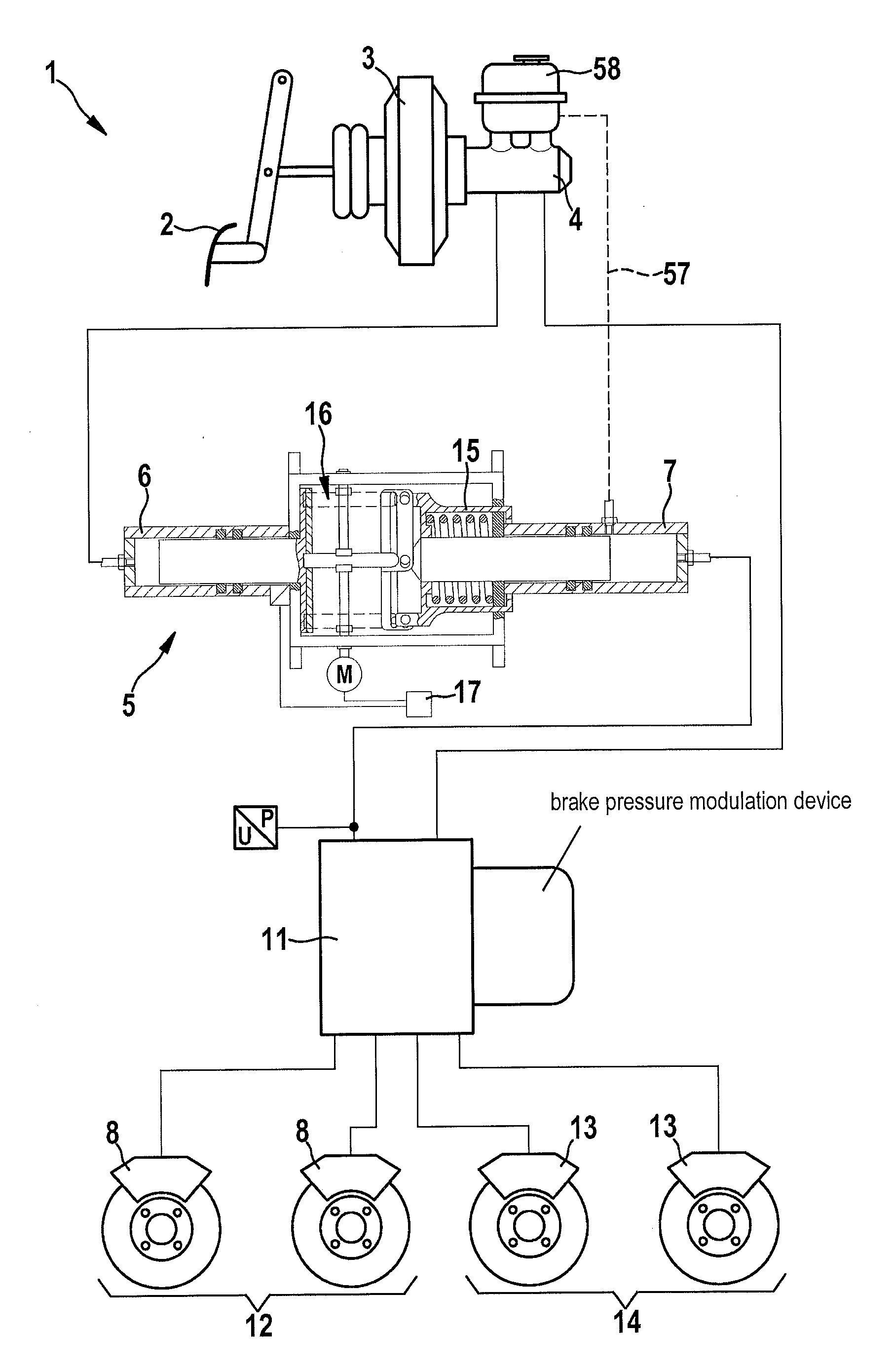
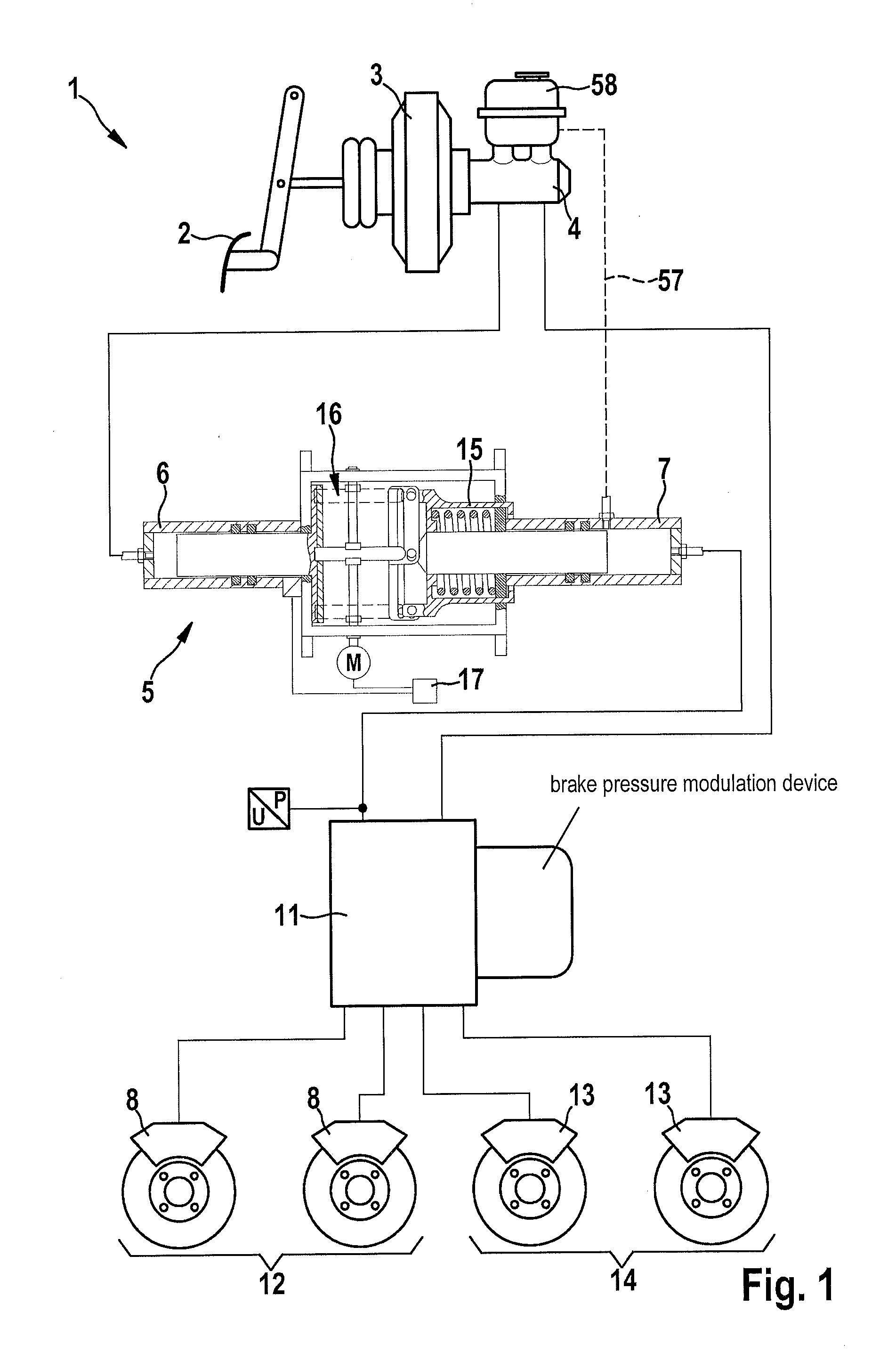
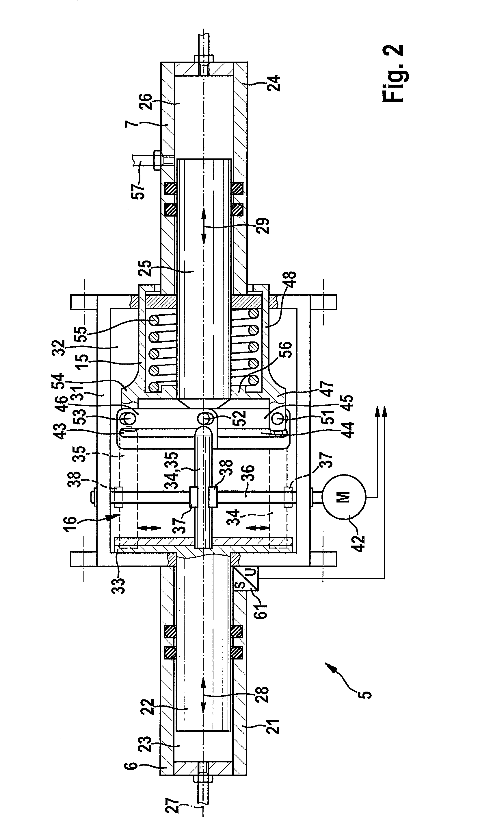
[0012]Below, a first exemplary embodiment of the present invention is explained in greater detail with reference to FIGS. 1 and 2.

[0013]Power-assisted braking system 1 is preferably a part of a hybrid or electric vehicle.

[0014]Power-assisted braking system 1 has a brake pedal 2, which actuates a master brake cylinder 4 with the aid of a brake booster 3. Brake booster 3 may take the form of, e.g., a vacuum brake booster or electromechanical brake booster. Master brake cylinder 4 is, in particular, a tandem brake cylinder.

[0015]Power-assisted braking system 1 further includes a pressure transmission device 5. At its inlet 6, pressure transmission device 5 is hydraulically connected to a chamber of mas...


PUM


Abstract

A pressure transmission device for a power-assisted braking system of a vehicle; at its inlet, the pressure transmission device being connectible in a hydraulically operative manner to a master brake cylinder of the power-assisted braking system, and at its outlet, the pressure transmission device being connectible in a hydraulically operative manner to a wheel brake cylinder of the power-assisted braking system; the pressure transmission device including an accumulator and a linkage, which transmits a pressure difference between the inlet and the outlet to the accumulator and stores it in this.

Description

BACKGROUND INFORMATION[0001]German Patent Application No. DE 10 2007 016 864 A1 describes a brake system for a vehicle, the brake system including an electromechanically boosted braking element and a pedal simulator, which is used for conveying a haptic braking feel to the driver in a usual manner. The brake system is manufactured as a brake-by-wire system, in which the movement of the brake pedal is measured sensorially and actuating signals for actuating an electric brake actuator in the braking element are generated by a control unit. A mechanical through-grip device is situated between the brake pedal and the braking element, the mechanical through-grip device being decoupled in the normal case, however, due to the design as a brake-by-wire system, and only being used in emergencies, such as a failure of the electromechanical brake boosting, in which case the force exerted on the brake pedal by the driver is used as the actuating force for the braking element. On the other hand,...

Claims


Application Information

Patent Timeline
Patent Type & Authority Applications(United States)
IPC IPC(8): B60T13/14B60T13/58
CPCB60T13/14B60T13/586B60T8/4266B60T8/441B60T8/489
Inventor MAYER, JOCHEN
Owner ROBERT BOSCH GMBH
Why Eureka
Try Eureka