Plasma cutter having high power density

a plasma cutter and power density technology, applied in plasma welding equipment, welding equipment, manufacturing tools, etc., can solve the problems of affecting the performance of the system, relatively low switching frequency and low power density, and adding weight, size, and cost to the plasma cutting system

Active Publication Date: 2013-02-12
ILLINOIS TOOL WORKS INC
View PDF39 Cites 49 Cited by
  • Summary
  • Abstract
  • Description
  • Claims
  • Application Information

AI Technical Summary

Problems solved by technology

The power output and flow of the gas can affect the performance of the system.
Additionally, the use and configuration of these components may result in relatively low switching frequencies and low power densities.
Further, these converters and other devices may add weight, size, and cost to the plasma cutting system.

Method used


Image

  • Plasma cutter having high power density
  • Plasma cutter having high power density
  • Plasma cutter having high power density

Examples


Embodiment Construction

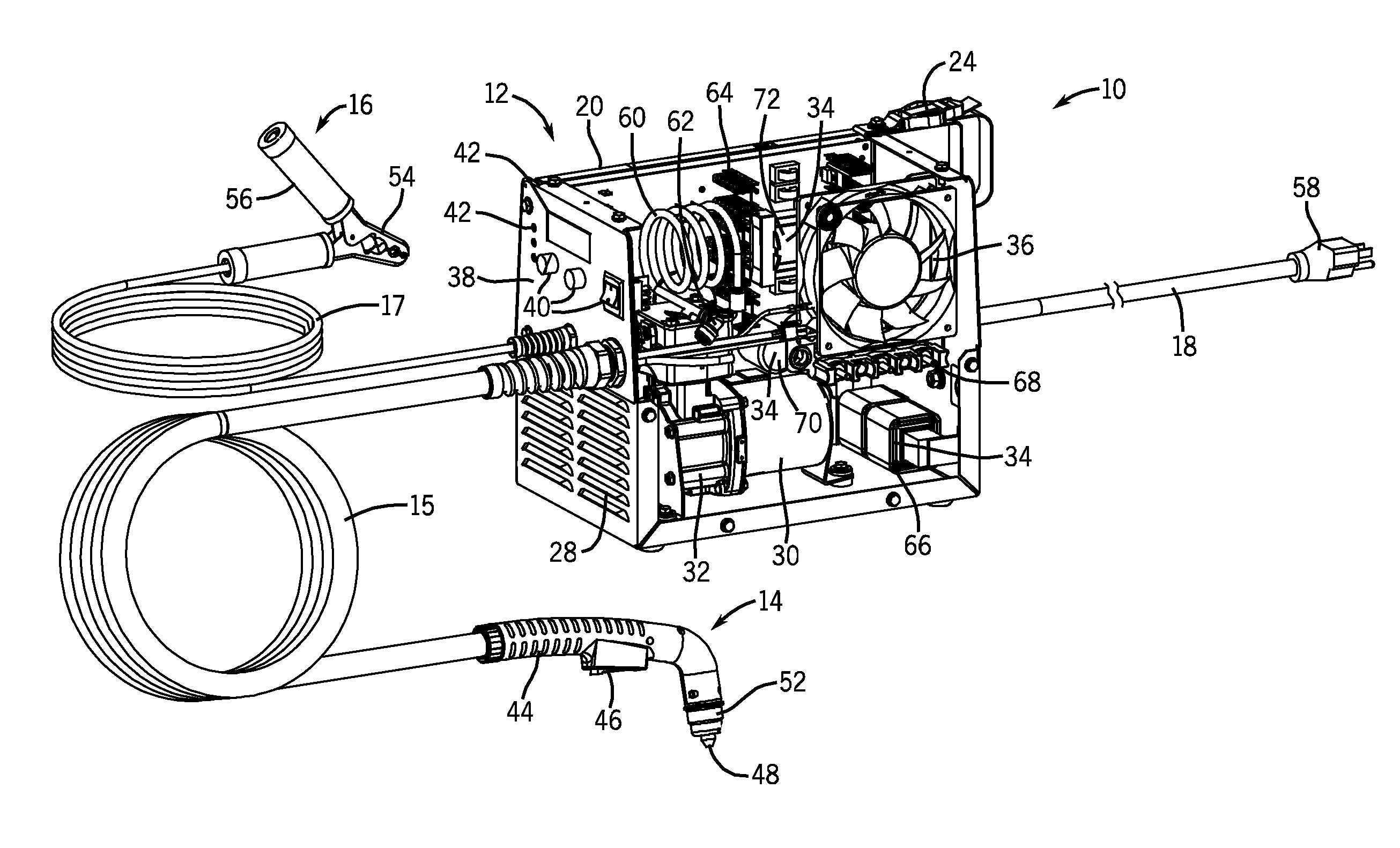
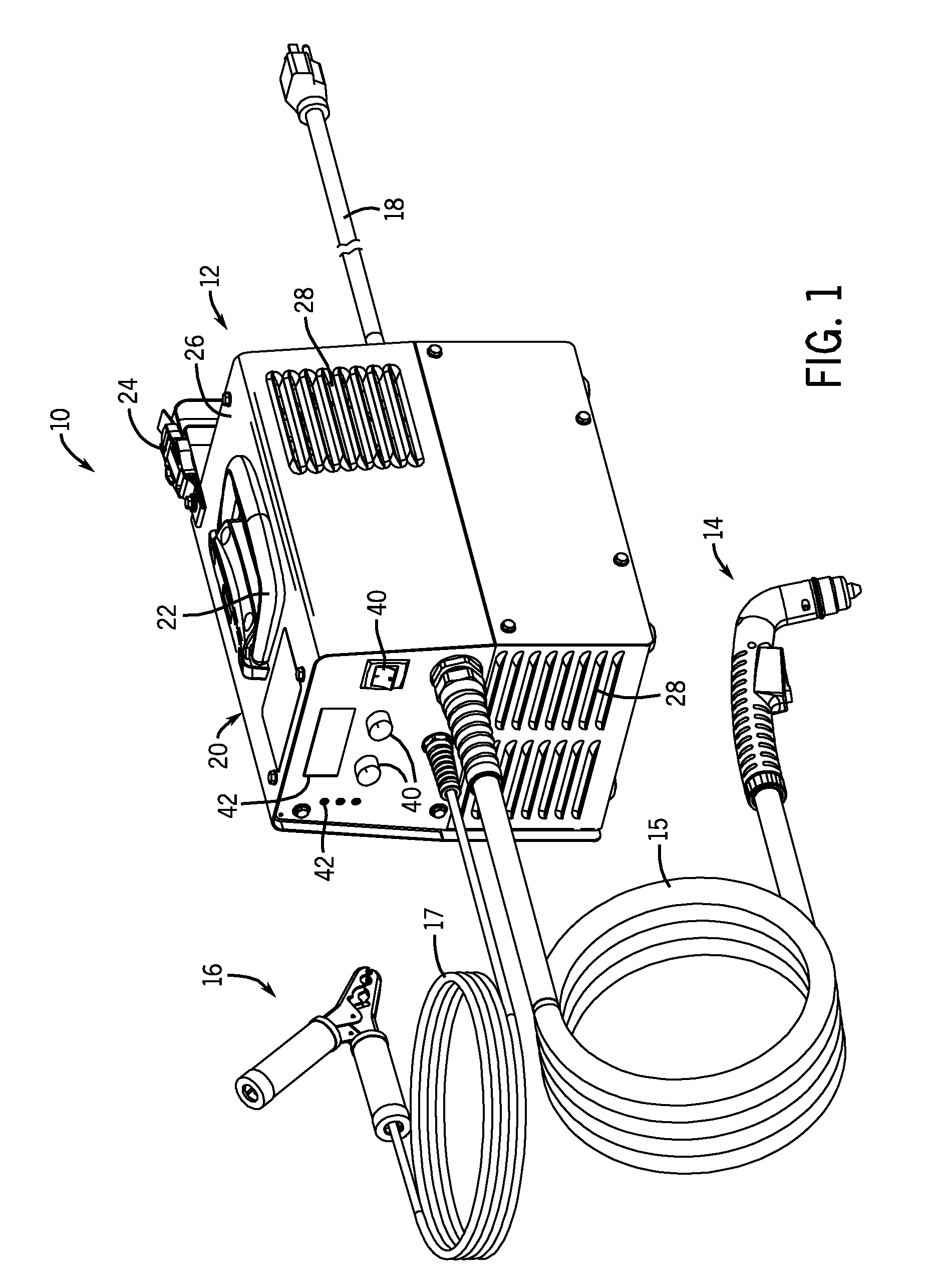
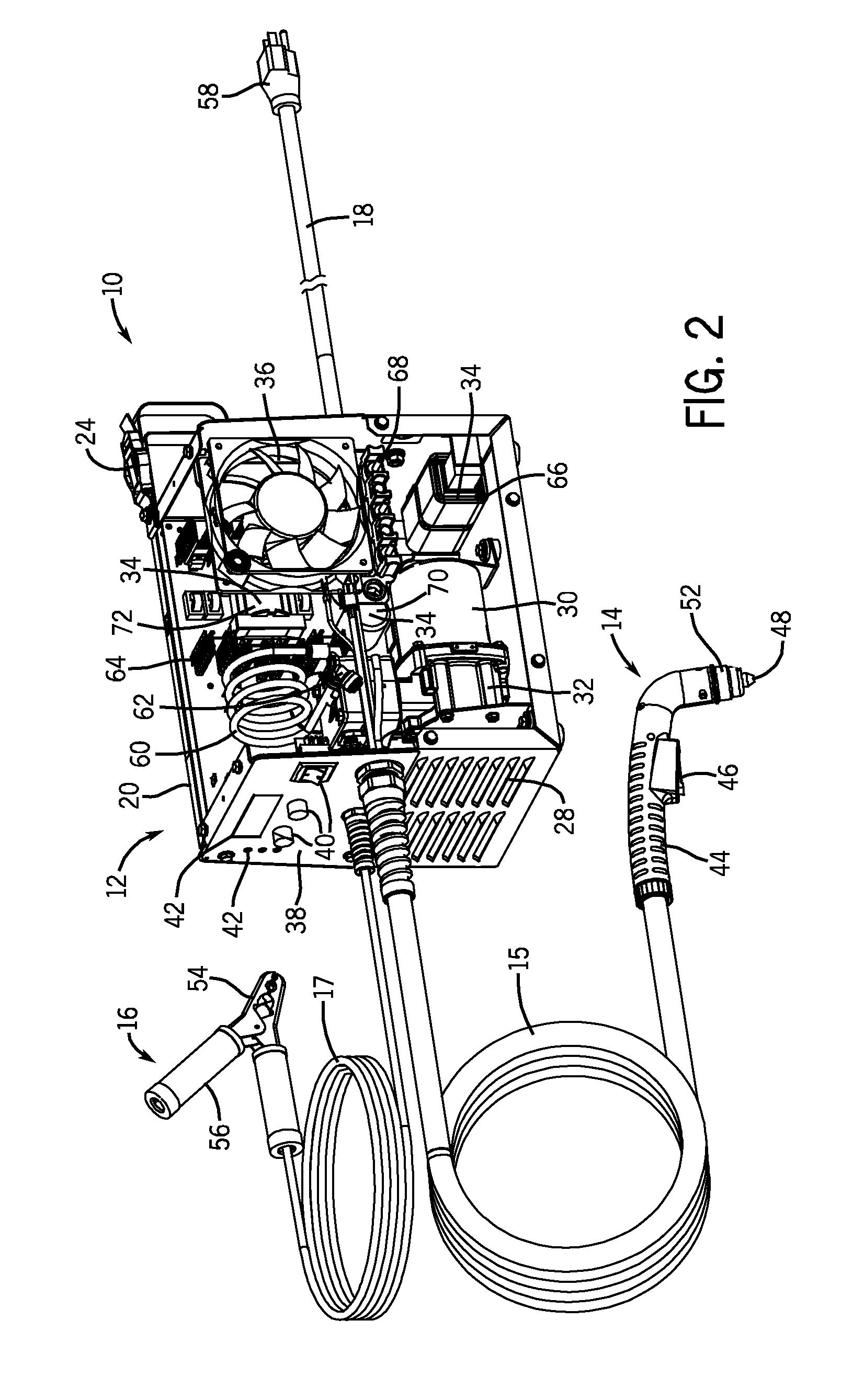
[0014]Referring now to the drawings, FIGS. 1 and 2 are partial perspective views illustrating an embodiment of a portable plasma cutting system 10 having a high power density. For example, one embodiment of the system 10 has 2.6 W per cubic inch and 103.4 W per pound. The system 10 may include high-frequency (e.g., greater than 200 kHz) power converters, foil wound transformers, and / or planar transformers to achieve such high power densities. Specifically, FIG. 1 illustrates the system 10 with access panels completely assembled to close internal components, whereas FIG. 2 illustrates an entire side panel assembly removed to provide a better view of the internal features and components of the system 10. As discussed in further detail below, embodiments of the system 10 may include a printed circuit board (PCB) having components for a main power converter and a motor power converter mounted to the PCB.

[0015]The illustrated plasma cutting system 10 includes a torch power unit 12 couple...


PUM

PropertyMeasurementUnit
switching frequencyaaaaaaaaaa
weightaaaaaaaaaa

Abstract

Systems and methods are provided for a torch power system having a high power density. In one embodiment, a system is provided that includes a torch power unit having a compressor and power electronics that include one or more power converters, wherein the torch power unit has a power output density of at least 2 watts per cubic inch, 80 watts per pound, or a combination thereof. A power conversion assembly for a torch power unit is provided that includes a single circuit board, a torch power converter mounted on the single circuit board, and a non-torch power converter mounted on the single circuit board. An electrical torch system is also provided that includes a circuit board and a power converter coupled to the circuit board, wherein the power converter includes a planar transformer, a foil wound transformer, or a combination thereof.

Description

BACKGROUND[0001]The invention relates generally to metal cutting and welding systems, and more particularly to portable power units for such systems.[0002]Some torch systems, such as a plasma cutting system, use plasma (e.g., high temperature ionized gas) to cut metal or other electrically conductive material. In general, an electrical arc converts a gas (e.g., compressed air) into plasma, which is sufficiently hot to melt the work piece while the pressure of the gas blows away the molten metal. The power output and flow of the gas can affect the performance of the system.[0003]Such plasma cutting systems may be portable and only require a power source for operation. As portable plasma cutting systems become smaller and less costly to manufacture, such plasma cutting systems may be targeted at the consumer market. However, such systems must provide a relativity high level of power output yet still maintain the portability necessary for the consumer market. Typically, the power conve...

Claims


Application Information

Patent Timeline
Patent Type & Authority Patents(United States)
IPC IPC(8): B23K10/00
CPCB23K10/00Y10T29/49002
Inventor SALSICH, ANTHONY VAN BERGEN
Owner ILLINOIS TOOL WORKS INC
Why Eureka
Try Eureka