Device for the plasma treatment of gases

a gas treatment and gas technology, applied in gas treatment, chemical vapor deposition coating, coatings, etc., can solve the problems of affecting the cooling of the tube, affecting the cooling effect of the tube, and low operating sensitivity to variable operating conditions

Inactive Publication Date: 2002-05-02
LAIR LIQUIDE SA POUR LETUDE & LEXPLOITATION DES PROCEDES GEORGES CLAUDE
View PDF7 Cites 70 Cited by
  • Summary
  • Abstract
  • Description
  • Claims
  • Application Information

AI Technical Summary

Benefits of technology

0038] the ignition means comprise a wire-like rod made of electrically conducting material, especially tungsten, extending towards the free end of the injector and connected to a low-frequency or radio-frequency high-voltage supply, and movement means for moving it closer to or further away from the vicinity of the free end;

Problems solved by technology

These gas treatment devices, although advantageous in terms of conversion yield, energy efficiency and low operating sensitivity to variable operating conditions, have a major drawback in so far as they are ill-suited or not very suitable for the treatment of gases whose decomposition gives an appreciable amount of solid materials, generally in powder form.
This is because these materials may block the tube through which the gas to be treated flows and in which the discharge is created, or, at the very least, they may modify its initially optimized internal geometry, interfere with heat exchange and impede the cooling of the tube, or may even impair the dielectric properties of the latter and disturb the propagation of the surface wave.
However, its architecture is relatively sophisticated and its construction is quite complex and expensive.
In addition, it is intrinsically difficult to provide the gas circuit with very good sealing.
This is a very serious drawback in the case of the treatment of gases containing impurities or effluents whose conversion gives dangerous gases (for example, corrosive halogenated compounds) or else gases of high added value (krypton and xenon).
This may pose impurity recondensation problems.

Method used


Image

  • Device for the plasma treatment of gases
  • Device for the plasma treatment of gases
  • Device for the plasma treatment of gases

Examples


Embodiment Construction

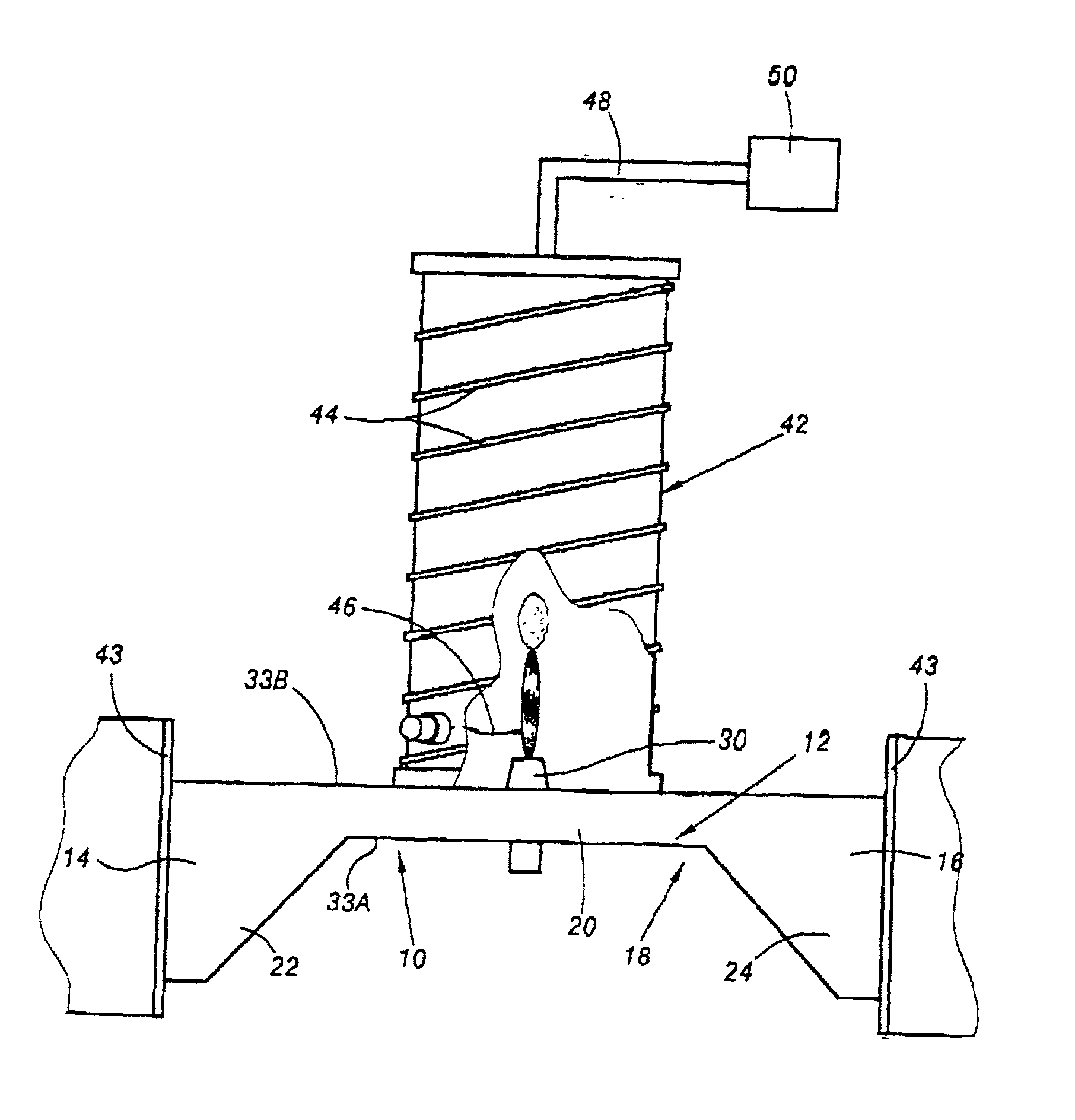
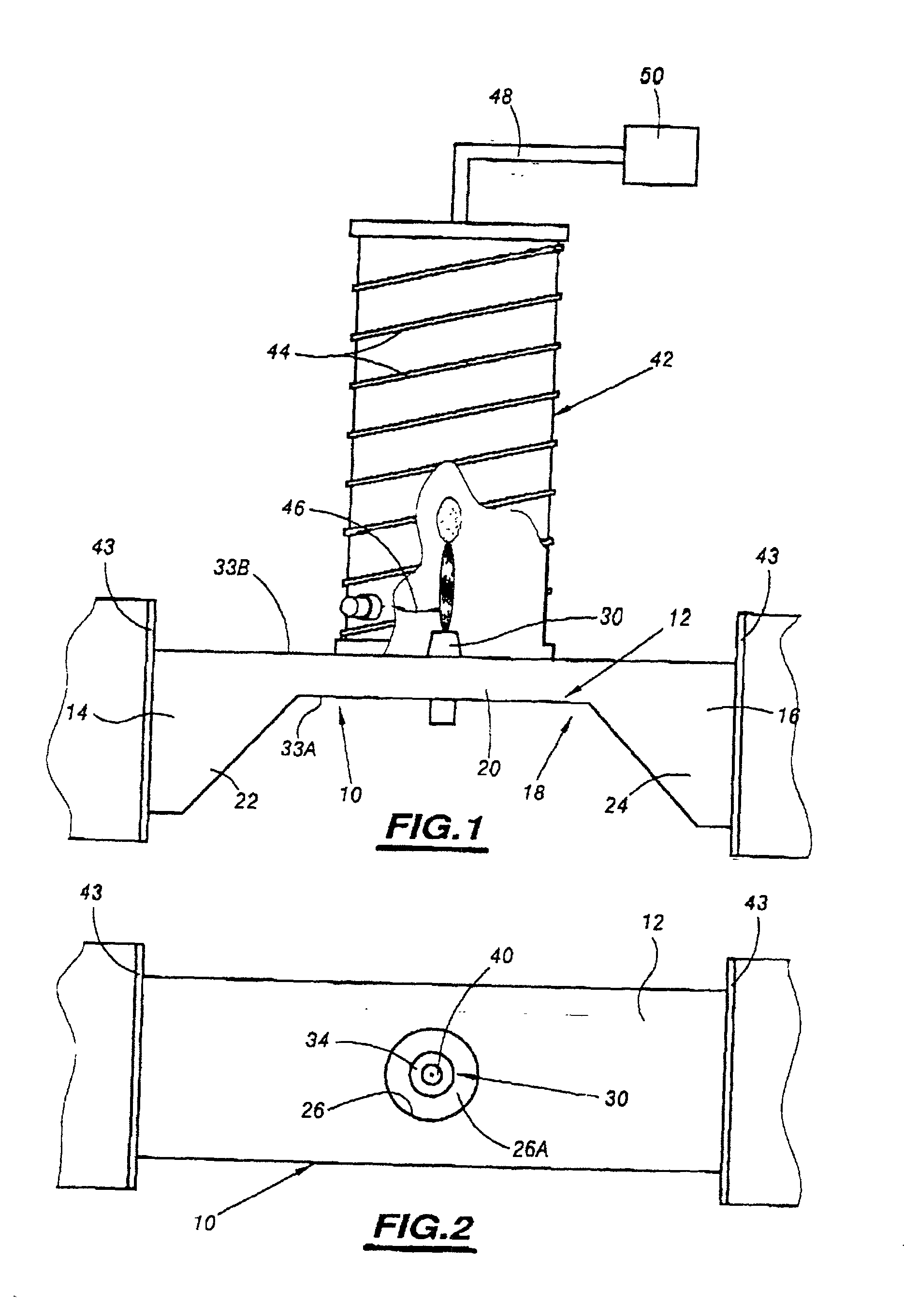
[0052] FIGS. 1 and 2 show, schematically, a device for the plasma treatment of gases according to the invention, denoted by the overall numerical reference 10, seen from the side and from above, respectively.

[0053] The device 10 consists mainly of a hollow waveguide structure 12 of longitudinal shape and made of an electrically conducting material suitable for the envisaged use, particularly a metal. Preferably, it has a rectangular cross section and a plane of symmetry lying in the plane of FIG. 1, that is to say parallel to the small faces of the structure 12.

[0054] The structure 12 has two open ends 14 and 16, one intended to be connected to a microwave generator (not shown) and the other intended to be connected to means suitable for forming an adjustable short circuit, preferably a conducting plate placed transversely and longitudinally adjustable so that the impedance can be adjusted.

[0055] Between the two ends 14 and 16, the structure 12 has a region 18 of reduced cross secti...


PUM

PropertyMeasurementUnit
diameteraaaaaaaaaa
diameteraaaaaaaaaa
diameteraaaaaaaaaa

Abstract

Provided is a device for the microwave-sustained plasma treatment of gases, which comprises a hollow structure forming a waveguide intended to be connected to a microwave generator, and means for making the gas to be treated flow through the said structure in a region in which the amplitude of the electric field associated with the incident wave is high. The means for making the gas flow comprise a plasma torch for producing a plasma in the gas. The torch comprises an injector made of an electrically conducting material mounted on a first large face of the said structure and extending so as to project through an orifice made in a second large face opposite the said first large face. A gap for passage of the incident waves lies around the injector.

Description

[0001] The present application claims priority to French Application No. 00 13840, filed Oct. 27, 2000, which is hereby incorporated by reference in its entirety.[0002] 1. Field of the Invention[0003] The present invention relates to a device for the plasma treatment of gases, in which the gas to be treated is excited by the plasma.[0004] 2. Description of Related Art[0005] Devices for the plasma, especially microwave-sustained plasma, treatment of gases of this type generally comprise a hollow structure forming a waveguide intended to be connected to a microwave generator and means for making the gas to be treated flow through the said structure in a region in which the amplitude of the electric field associated with the incident wave is high, and preferably a maximum.[0006] The principle of these gas treatment techniques consists in creating, by means of an electrical discharge in a majority gas or plasma gas (argon, nitrogen, krypton, xenon, etc.) containing impurities or gaseous...

Claims


Application Information

Patent Timeline
Patent Type & Authority Applications(United States)
IPC IPC(8): B01J19/08H01J37/32H05H1/30H05H1/34
CPCB01D53/32H05H1/30B01D2259/818B01J19/088B01J19/126B01J2219/0871B01J2219/0894B01J2219/1215B01J2219/1236B01J2219/1269B01J2219/1281B01J2219/1284B01J2219/1293H01J37/32192B01D2259/806H01J37/32
Inventor MOISAN, MICHELZENON, ZAKRZEWSKIKEROACK, DANIELLEROSTAING, JEAN-CHRISTOPHE
Owner LAIR LIQUIDE SA POUR LETUDE & LEXPLOITATION DES PROCEDES GEORGES CLAUDE
Why Eureka
Try Eureka