Security apparatus with conductive ribbons

a technology of conductive ribbons and security apparatuses, applied in the field of electronic article surveillance (eas) and security, can solve the problems of further complicating the unauthorized attempt to disarm the security apparatus by changing the passcode, and achieve the effect of facilitating the facilitation of the attaching of the housing

a technology of conductive ribbons and security apparatuses, applied in the field of electronic article surveillance (eas) and security, can solve the problems of further complicating the unauthorized attempt to disarm the security apparatus by changing the passcode, and achieve the effect of facilitating the facilitation of the attaching of the housing

US8373565B2Inactive Publication Date: 2013-02-12YANG XIAO HUI

Image

  • Security apparatus with conductive ribbons
  • Security apparatus with conductive ribbons
  • Security apparatus with conductive ribbons

Examples


Embodiment Construction

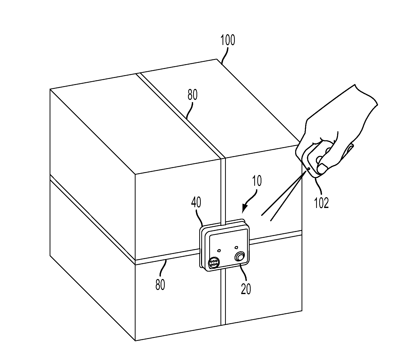
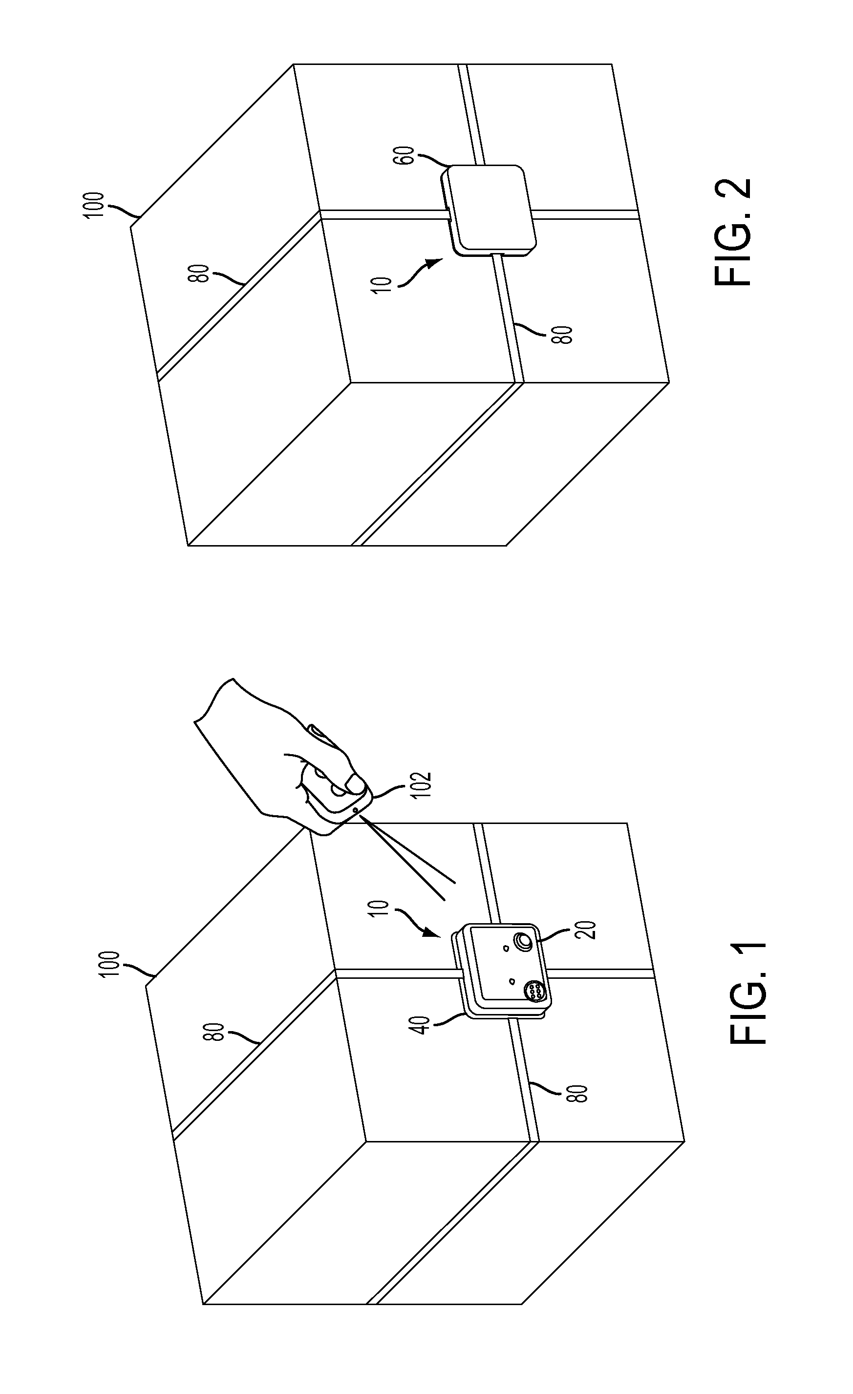
[0034]FIG. 1 is a front perspective view of an object 100 being protected by an attached embodiment of security apparatus 10. In the embodiment shown in FIG. 1, base plate 40 is attached to object 100 and housing 20 is attached to base plate 40 with ribbons 80 retained between them. Ribbons 80 pass around object 100 and intersect on the opposite side. FIG. 2 is a rear perspective view of object 100 which shows that opposite side with ribbon pad 60 installed on it, and ribbons 80 intersecting on ribbon pad 60. Ribbons 80 are electrically conductive along their lengths and, depending on their embodiment, may be electrically conductive at their surfaces or may have electrically conductive elements not exposed at their surfaces.

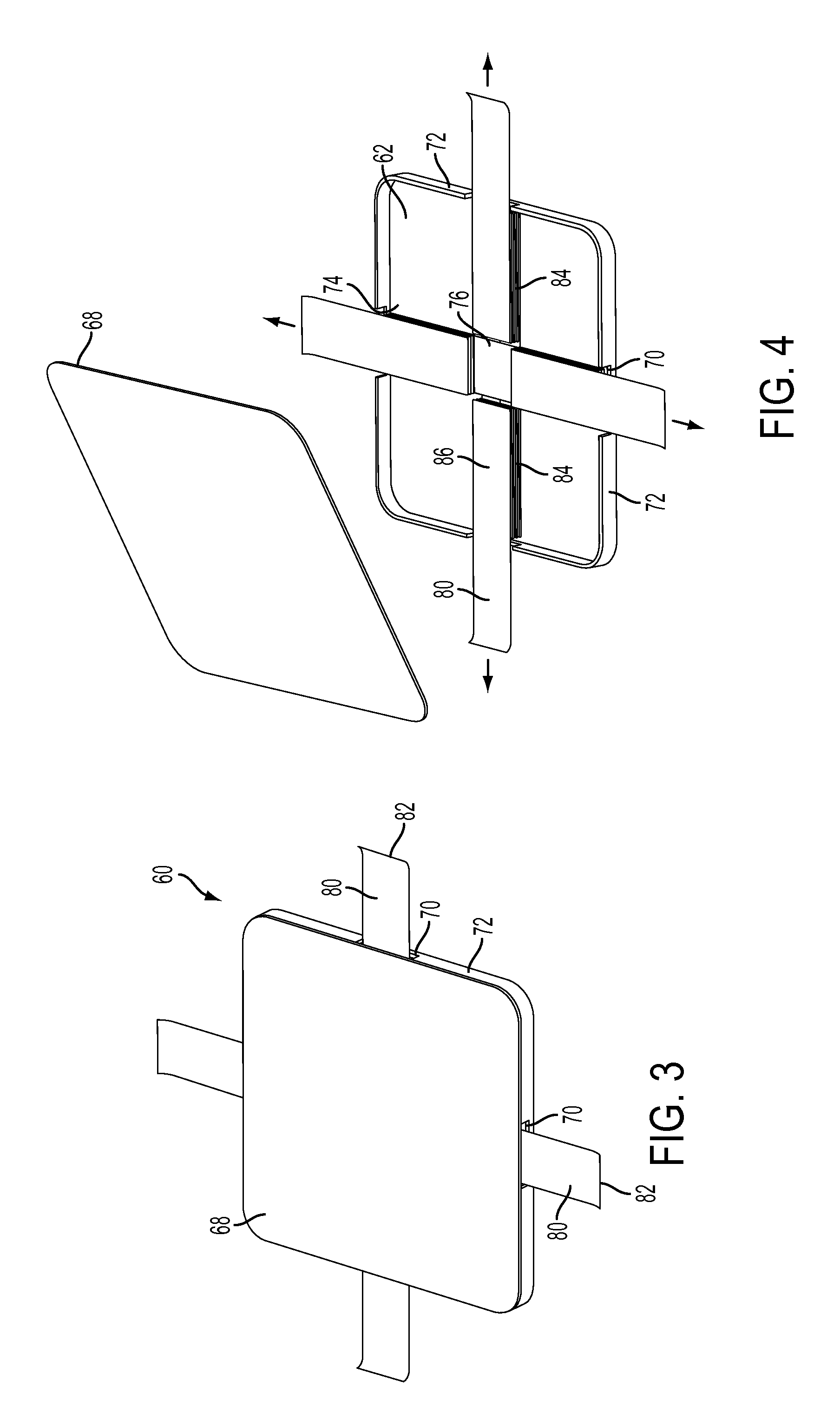
[0035]FIG. 3 is a top perspective view of ribbon pad 60 with a cover 68. Extending ends 82 of ribbons 80 extend out of ribbon apertures 70 in ribbon pad 60. In the embodiment of ribbon pad 60 shown in FIG. 3, ribbon apertures 70 penetrate sides 72 of ribbon pad 6...


PUM


Abstract

An electronic article surveillance (EAS) security apparatus is comprised of a housing, base plate, ribbon pad, and electrically conductive ribbons. In one embodiment, the ribbons pre-attached to the ribbon pad and extend from the ribbon pad. The ribbon pad and base plate on installed on opposite sides of an object to be protected. The ribbons are extended around the object and their extended ends attached to the base plate. The housing has electrical contacts and encloses electronics and is attached to the base plate so that the electrical contacts complete circuits through the ribbons. The electronics in the housing monitor the ribbons to detect unauthorized removal of the apparatus. A switch on the bottom of the housing detects that the housing is attached to a plate and object. The apparatus has a locking mechanism to maintain the housing and plate together, which can be released by application of a magnet.

Description

CROSS REFERENCE TO RELATED APPLICATIONS[0001]This application is a continuation-in-part of U.S. application Ser. No. 13 / 151,106, which in turn is a continuation-in-part of U.S. patent application Ser. No. 12 / 815,380 filed on Jun. 14, 2010, (now U.S. Pat. No. 8,334,776), and U.S. patent application Ser. No. 13 / 010,571 filed on Jan. 20, 2011. U.S. patent application Ser. No. 12 / 815,380 (now U.S. Pat. No. 8,334,776) in turn claims priority to U.S. Provisional Application 61 / 186,889 filed on Jun. 14, 2009. U.S. patent application Ser. No. 13 / 010,571 is a continuation-in-part application based on U.S. patent application Ser. No. 12 / 726,879 filed on Mar. 18, 2010(now U.S. Pat. No. 8,305,219). U.S. patent application Ser. No. 12 / 726,879 (now U.S. Pat. No. 8,305,219) is a continuation-in-part application based on U.S. patent application Ser. No. 12 / 498,367, filed on Jul. 7, 2009 (now U.S. Pat. No. 8,274,391). U.S. patent application Ser. No. 12 / 498,367 is a continuation-in-part application ...

Claims


Application Information

Patent Timeline
12 Feb 2013
Publication
US8373565B2
IPC
G08B13/14
CPC
G08B13/1463; G08B13/2434; B65D2211/00
Inventors
YANG, XIAO HUI