
Mode based metal strip stabilizer

a metal strip and stabilizer technology, applied in the direction of measuring devices, instruments, manufacturing tools, etc., can solve the problem that no information from other sensor devices is used to correct or adapt the generated magnetic force, and achieve the effect of reducing the movement of the strip and reducing the vibration of the strip

Active Publication Date: 2013-02-12
ABB (SCHWEIZ) AG
View PDF7 Cites 0 Cited by
  • Summary
  • Abstract
  • Description
  • Claims
  • Application Information

AI Technical Summary

Benefits of technology

The present invention provides a method and system for controlling movement of a steel sheet or strip being processed in a steel processing line. This system acts as a damper of strip vibration, reducing strip movement and controlling strip shape. The method also includes using actuators to minimize the variance of coefficients, which further damps vibrations of the strip. Additionally, a non-contact sensor measuring the distance to the strip is located in proximity to the non-contact actuator stabilizing the movement of the strip. Overall, this technology ensures a steady operation of the processing line and prevents operational problems such as strip vibration and shape loss.

Problems solved by technology

No information from other sensor devices is used to correct or adapt the generated magnetic force from a device.

Method used


Image

  • Mode based metal strip stabilizer
  • Mode based metal strip stabilizer
  • Mode based metal strip stabilizer

Examples


Embodiment Construction

[0041]Detailed descriptions of the preferred embodiment are provided herein. It is to be understood, however, that the present invention may be embodied in various forms. Therefore, specific details disclosed herein are not to be interpreted as limiting, but rather as a basis for the claims and as a representative basis for teaching one skilled in the art to employ the present invention in virtually any appropriately detailed system, structure or manner.

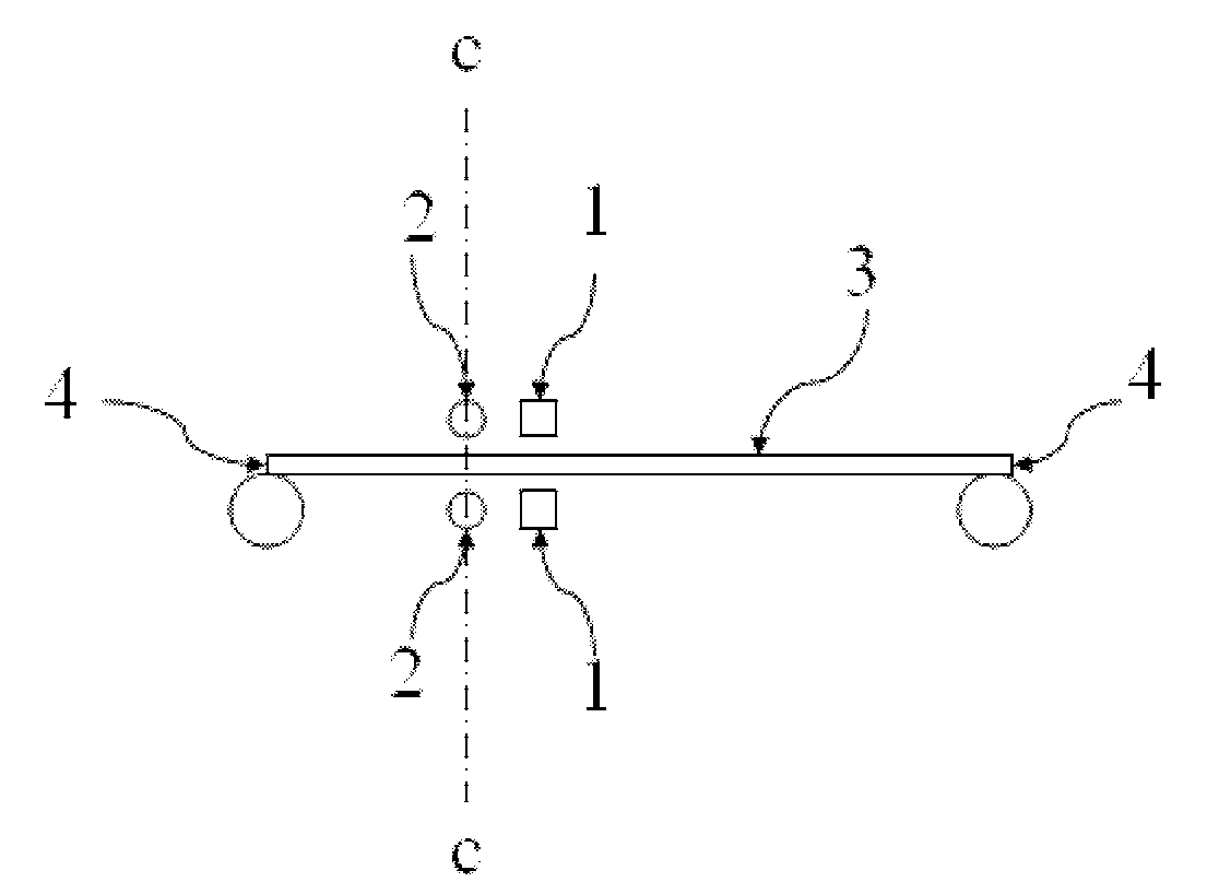
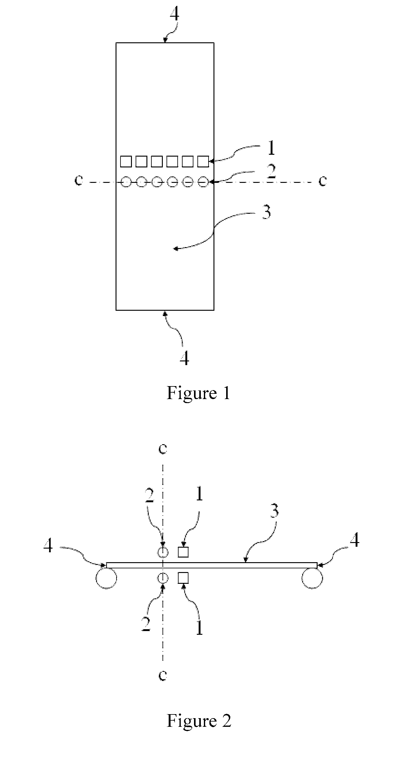
[0042]FIG. 1 shows one arrangement of sensors and actuators vertical to the strip 3 surface according to an embodiment of the present invention. The metal strip 3 profile is suspended or fixed at the short side 4. Position sensors 2, which could be inductive position sensors, and actuators 1, which could be electromagnets, are arranged across the strip. The electromagnets are generating magnetic forces acting at right angles on the metal strip and by controlling the current to the electromagnets the force on the metal strip can be co...


PUM

PropertyMeasurementUnit
vibration dampingaaaaaaaaaa
distanceaaaaaaaaaa
distance measurementsaaaaaaaaaa

Abstract

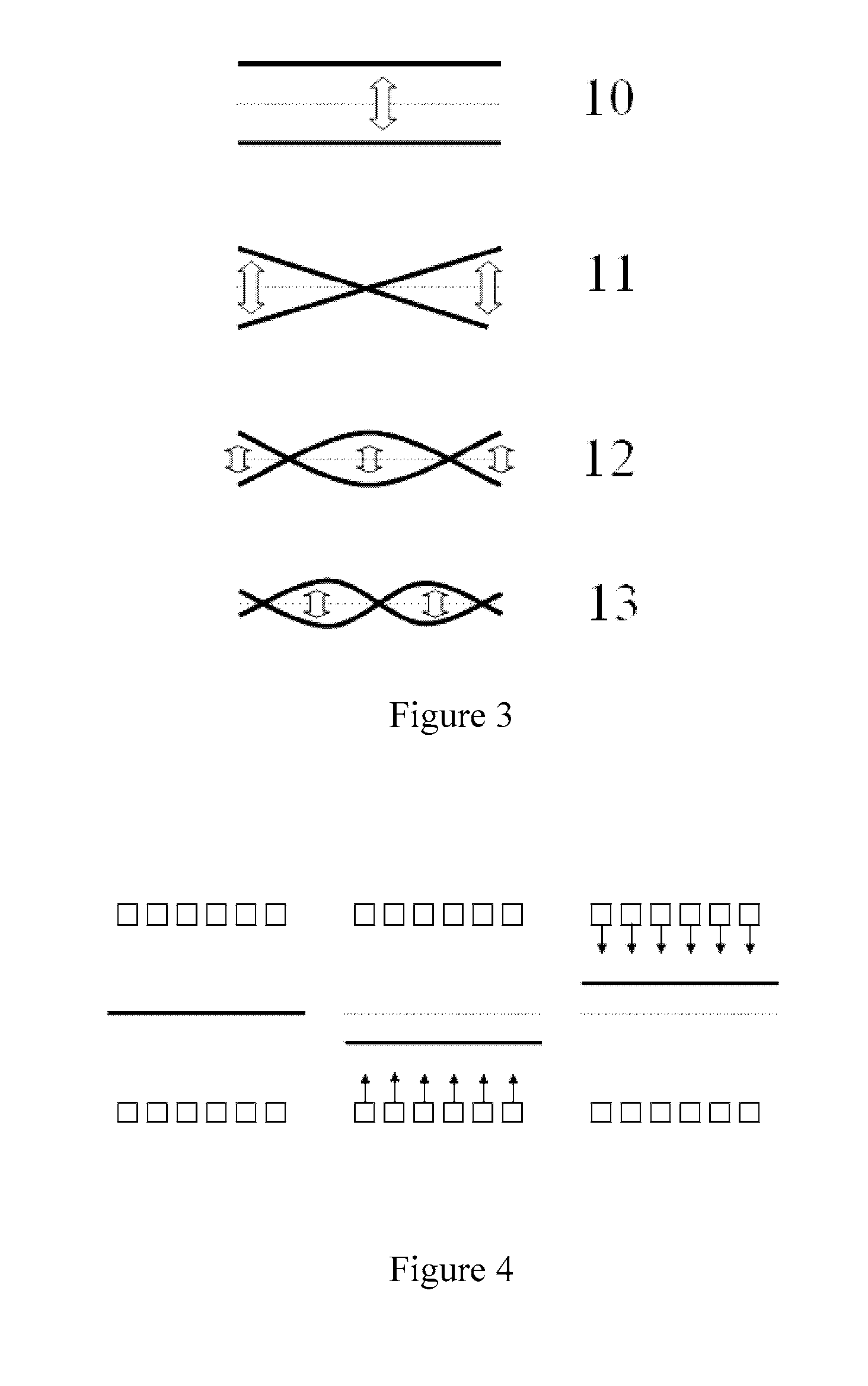
A method for vibration damping and shape control of a suspended metal strip during continuous transport in a processing facility in a steel rolling line or surface treating line in a steel mill, where the method comprises the steps: measuring distance to the strip by a plurality of non-contact sensors; and generating a strip profile from distance measurements; decomposing the strip profile to a combination of mode shapes; determining coefficients for the contribution from each mode shape to the total strip profile; and controlling the strip profile by a plurality of non-contact actuators based on a combination of mode shapes.

Description

CROSS-REFERENCE TO RELATED APPLICATIONS[0001]The present application is a continuation of pending International patent application PCT / EP2007 / 059189 filed on Sep. 3, 2007 which designates the United States, the content of which is incorporated herein by reference.FIELD OF THE INVENTION[0002]The present invention relates to a method and system for stabilizing and controlling the vibrations or shape of a metal strip or an elongated steel sheet or strip driven along the running surface of a processing facility in a steel rolling line or surface treating line in a steel mill.BACKGROUND OF THE INVENTION[0003]In the steel industry there is a need to stabilize i.e. reduce unwanted motions and vibrations of moving metal strips or sheets. The stabilization is especially important in hot-dip galvanizing lines.[0004]In hot-dip galvanizing lines, the metal strip to be galvanized is moved through a bath of molten zinc. When the metal strip leaves the zinc bath, an air-knife blows off the excess ...

Claims


Application Information

Patent Timeline
Patent Type & Authority Patents(United States)
IPC IPC(8): G06F19/00
CPCB21B37/007C23C2/40B21C51/00B21B37/68B21B39/00B21B38/02
Inventor LOFGREN, PETERMOLANDER, MATS
Owner ABB (SCHWEIZ) AG
Learn More