
Tool system

a tool system and tool technology, applied in the field of portable power tools, can solve the problems of not being able to accurately drill holes at a particular orientation and/or depth, not being able to accommodate a variety of attachments such as lights, stud finders, lasers, etc., and achieves smooth and precise movement along the length, convenient storage, and smooth and precise movement.

Active Publication Date: 2013-02-19
BEACHY ROBERT WISLER +2
View PDF73 Cites 26 Cited by
  • Summary
  • Abstract
  • Description
  • Claims
  • Application Information

AI Technical Summary

Benefits of technology

The present invention relates to a tool motor assembly for processing a work piece, which includes a tool motor, a guide assembly with a mast and a housing slide, and a conveniently mountable housing storage slide. The tool motor can smoothly and precisely move along the length of the mast, and the assembly also includes an accessory that can be easily stored separately from the tool motor. The technical effects of this invention are convenient and easy storage of the tool motor and accessories, and smooth and precise movement of the tool motor during processing of the work piece.

Problems solved by technology

But almost as a consequence of being so easy to use and portable, they are not inherently good at drilling precise, repeatable holes at a particular orientation and / or depth relative to the work piece.
In addition, they have storage and charging (for cordless models) challenges and don't accommodate a variety of attachments such as lights, stud finders, lasers, handles, etc.
While such alignment guides are helpful, they do not guarantee precise drilling.
“Bit guides” are simple and inexpensive, but not particularly adjustable or precise, because, at least in part, of the inherent problems associated with directly contacting the bit.
The advantage of such a system is that it can be very precise; the disadvantage is the cost, complexity and additional weight of the carriage (i.e. the part or assembly that is fixed to the housing and slides on the post(s) or mast(s)).
Such drill guides are complex and bulky, given the fact that they have an extra chuck.
One of the significant limitations of prior art “housing guide” drill guides is their inability to drill a sufficiently wide variety of holes in a precise, repeatable way.
But prior art “housing guides” do not include practical means for accurately and repeatedly drilling a pre-set distance from the edge of a work piece.
One guide, shown in U.S. Pat. No. 4,729,698, includes an adjustable edge guide, but the '698 edge guide is cumbersome due to use of a pair of sliding rods captured by tubular pieces and held in place by four set screws.
And no prior art drill guides, of any type, provide or accommodate a useful array of attachments and storage options.
For example, there's no convenient way to store the edge guide of the '698 patent when it's not in use; nor does the '698 edge guide provide additional functionality (that is, it is an edge guide and only an edge guide).

Method used


Image

  • Tool system
  • Tool system
  • Tool system

Examples


Embodiment Construction

[0097]The following detailed description of preferred embodiments will be broken down into five sections, namely (i) basic system; (ii) basic system operation; (iii) accessories; (iv) storage solutions; and (v) alternative embodiments.

Basic System

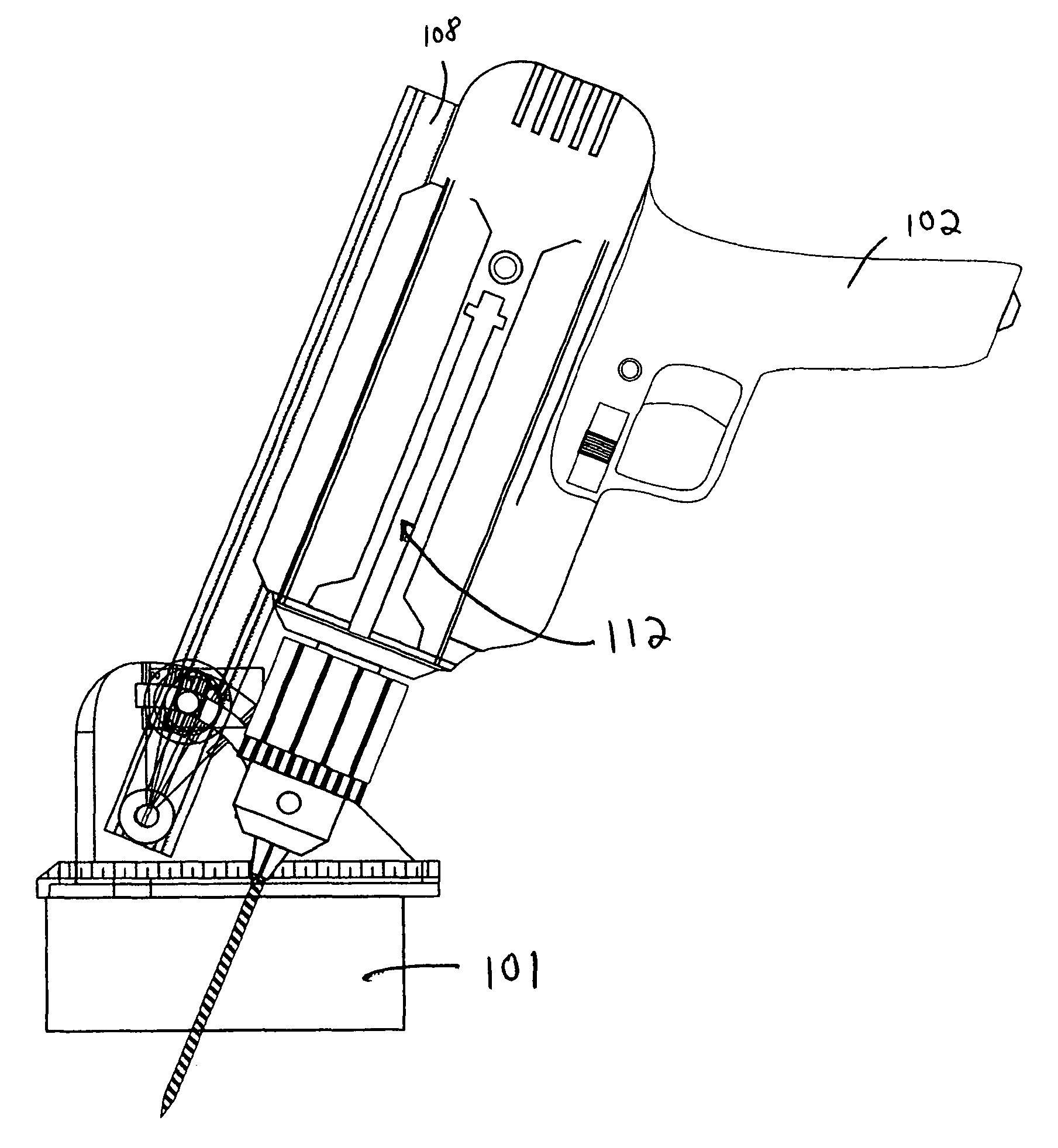
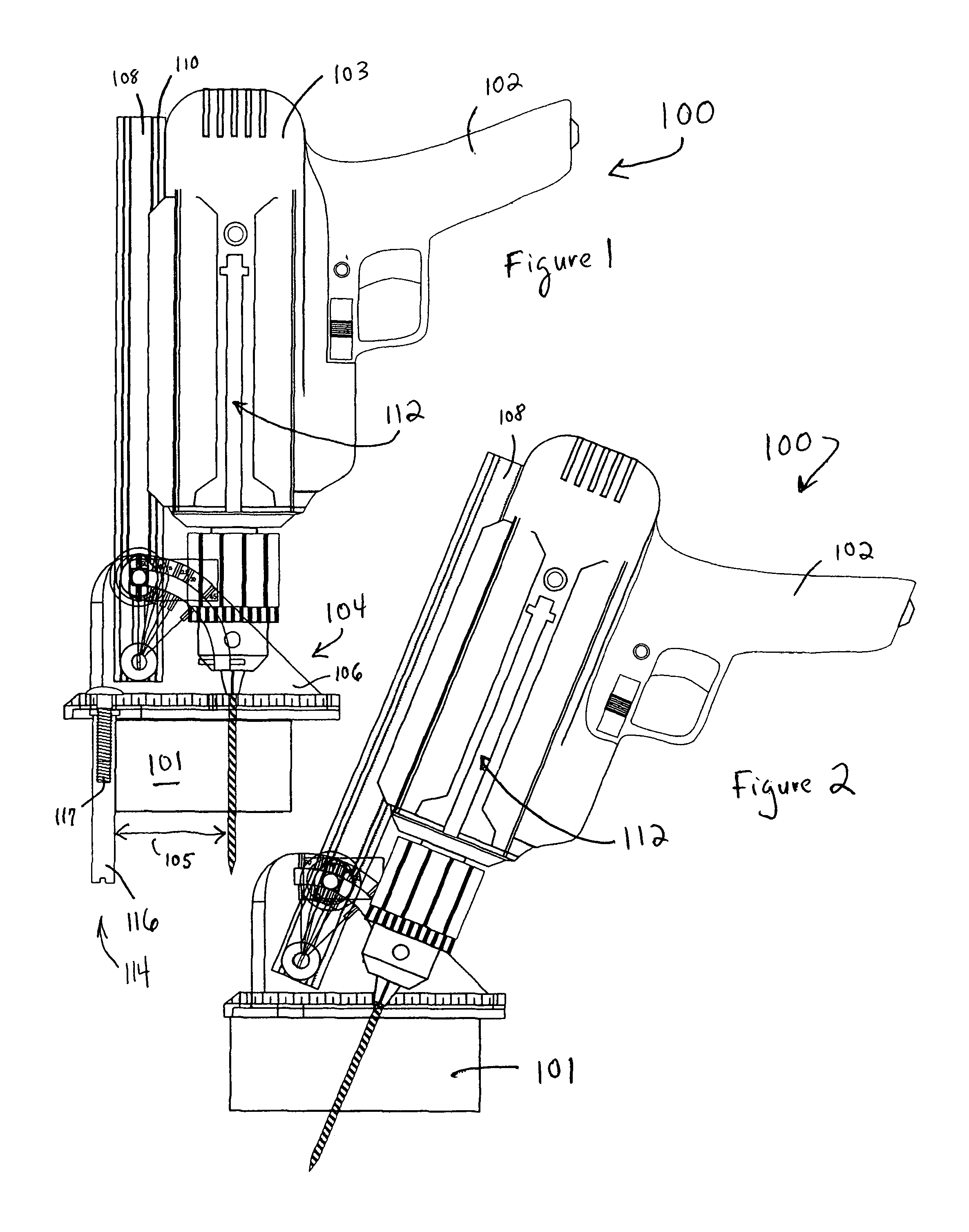
[0098]Referring to FIG. 1, a first preferred embodiment of a tool motor assembly according to the present invention is shown. More specifically, FIG. 1 shows a preferred drill motor assembly 100 capable of accurately and precisely drilling holes of various depths, edge offsets and angles in work piece 101. And, as noted above, a “drill” as that term is used herein, could be any powered (e.g., corded, cordless, electric, battery, pneumatic) handheld drill or driver. What's more, many aspects of the present invention could be applied to other types of tools. See, for example, the nail gun shown in FIGS. 60 and 61.

[0099]Preferred drill motor assembly 100 includes a drill motor 102, that itself includes a drill motor housing 103, and a separabl...


PUM

PropertyMeasurementUnit
angleaaaaaaaaaa
angleaaaaaaaaaa
anglesaaaaaaaaaa

Abstract

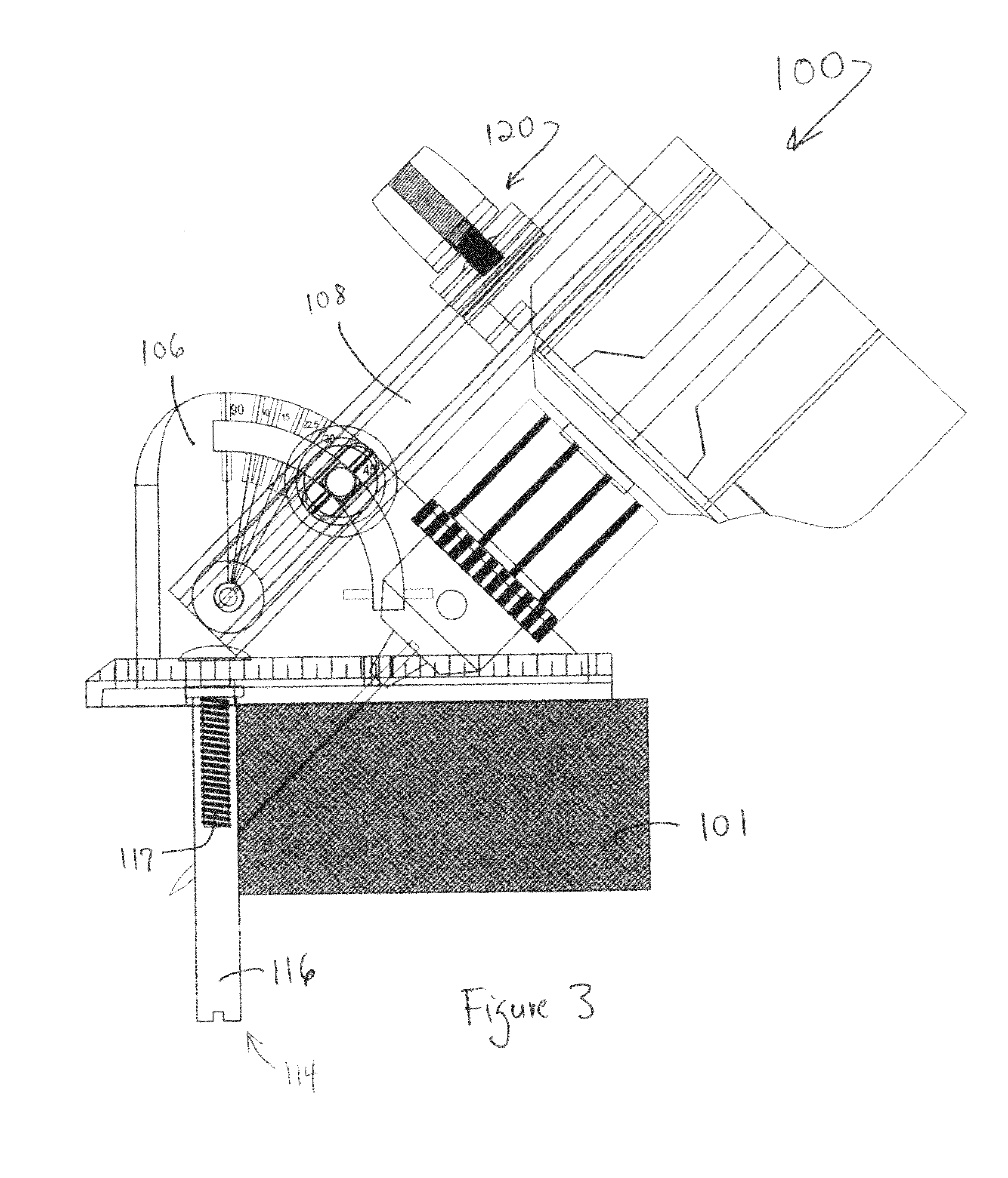
One embodiment of the present invention is a drill motor assembly (100) including a drill motor (102) and a housing guide assembly (104). The housing guide assembly in turn includes a base (106) and a mast (108) pivotally and adjustably attached thereto. A male slide (110) on the mast (108) slidably and precisely engages a female slide (112) on the drill motor (102). To drill a precise hole using the drill motor assembly (100), the operator simply adjusts the mast (108) to the desired angle relative to the base (106), engages the slides (110) and (112), activates the drill motor (102), and moves the drill motor (102) along the mast (108) until the drilling operation is completed. The present invention also includes a wide variety of accessories that can be connected to, and in some cases powered by, the drill motor (102); and a wide variety of storage options as well; and all of the attachments and storage options use the slides on the tool and accessories to facilitate use and / or storage of the various devices and components of the present invention.

Description

CROSS REFERENCE TO RELATED APPLICATIONS[0001]This application claims the benefit of one or more previously-filed copending provisional applications identified as follows: U.S. Provisional Application Ser. No. 60 / 802,987 filed on May 24, 2006 entitled Tool System, the entire contents of which are incorporated herein by reference.FIELD OF THE INVENTION[0002]The present invention relates generally to portable power tools; and more specifically to systems for (i) guiding and controlling portable power tools to enhance their precision and utility; and (ii) providing storage and attachment features for portable power tools, as well.BACKGROUND OF THE INVENTION[0003]Portable handheld power tools are pervasive. Such tools include, but are not limited to, saws, routers, sanders, screwdrivers, and of course, drills. Portable handheld drills, particularly corded and cordless electric drills, are uniquely useful portable power tools; and the present invention is particularly directed to handheld...

Claims


Application Information

Patent Timeline
Patent Type & Authority Patents(United States)
IPC IPC(8): B23B45/14
CPCB23B47/281B23B45/003B23B47/287B25F3/00B23B51/00B25H1/0042B23B2247/10Y10T408/564Y10T408/567Y10T29/5107Y10T408/21
Inventor BEACHY, ROBERT WISLERKAKUK, JAY JEFFREYBUCKLEY, ROBERT LAWRENCE
Owner BEACHY ROBERT WISLER
Learn More