Aircraft gas turbine engine counter-rotatable generator

a technology of electric generator and gas turbine engine, which is applied in the direction of machines/engines, mechanical energy handling, mechanical apparatus, etc., can solve the problems of reducing the ability to operate the engine properly, reducing the ability of the engine to achieve reasonable efficiency, and exceeding the efficiency of the booster

Active Publication Date: 2013-02-19
GENERAL ELECTRIC CO
View PDF29 Cites 25 Cited by
  • Summary
  • Abstract
  • Description
  • Claims
  • Application Information

AI Technical Summary

Problems solved by technology

Conventional boosters are extremely inefficient at low speeds and result in higher stage counts to achieve reasonable efficiencies.
When operating an aircraft engine at relatively low power levels, e.g., while idly descending from altitude, extracting electrical power from the engine mechanical power may reduce the ability to operate the engine properly.
At flight conditions where lower thrust and high electric power is required, such as approach, the core must run fast to keep up the electrical power demand but the result is more thrust which must be spoiled to maintain approach speeds, thus, reducing fuel efficiency.
The low-pressure (LP) engine spool provides an alternate source of power transfer, however, the relatively lower speed of the LP engine spool typically requires the use of a gearbox, as slow-speed electrical generators are often larger than similarly rated electrical generators operating at higher speeds.
Electrical generators operating off the LP rotor or spool require large generators due to low speeds of the LP rotor or gearboxes to increase speed.

Method used


Image

  • Aircraft gas turbine engine counter-rotatable generator
  • Aircraft gas turbine engine counter-rotatable generator
  • Aircraft gas turbine engine counter-rotatable generator

Examples


Embodiment Construction

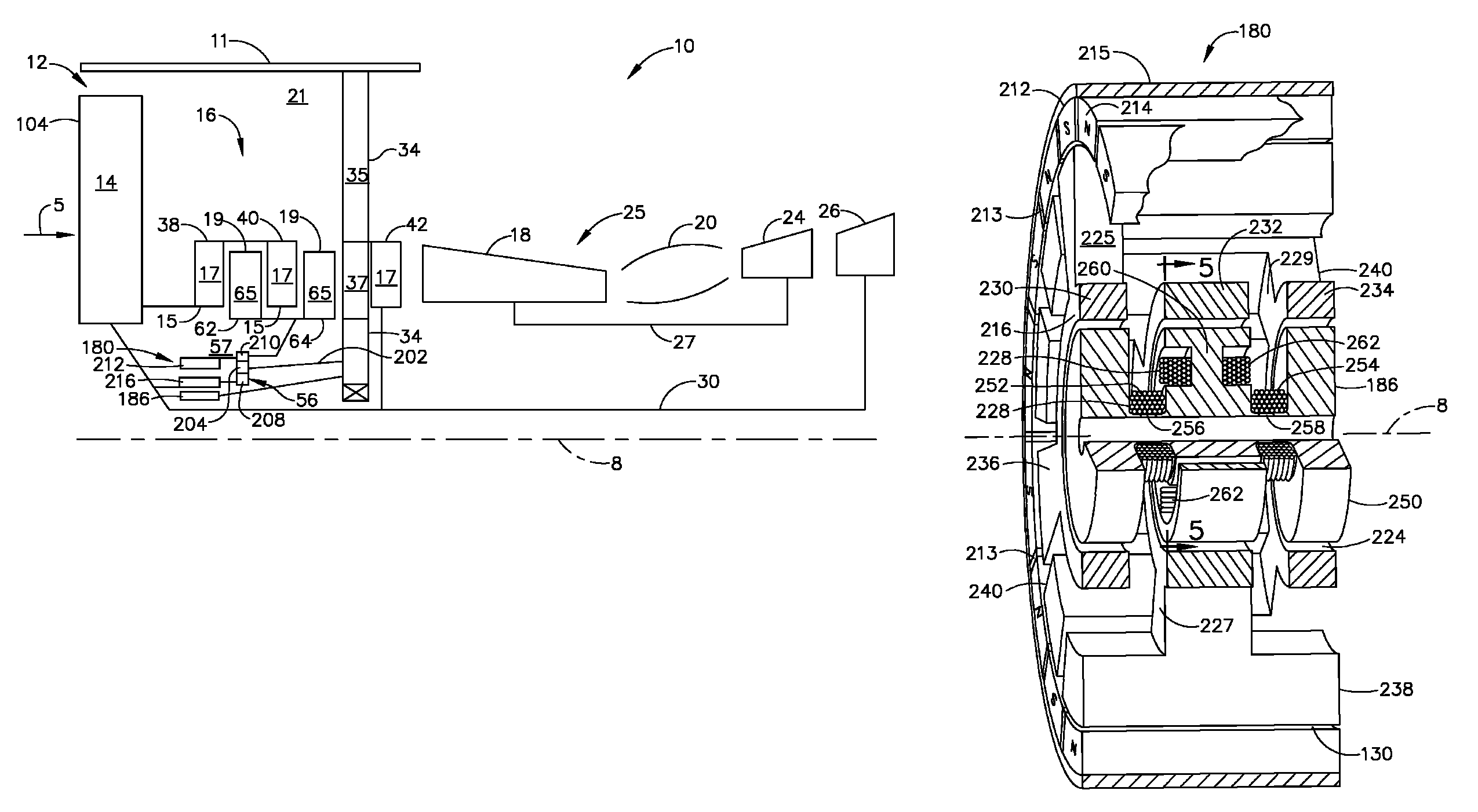
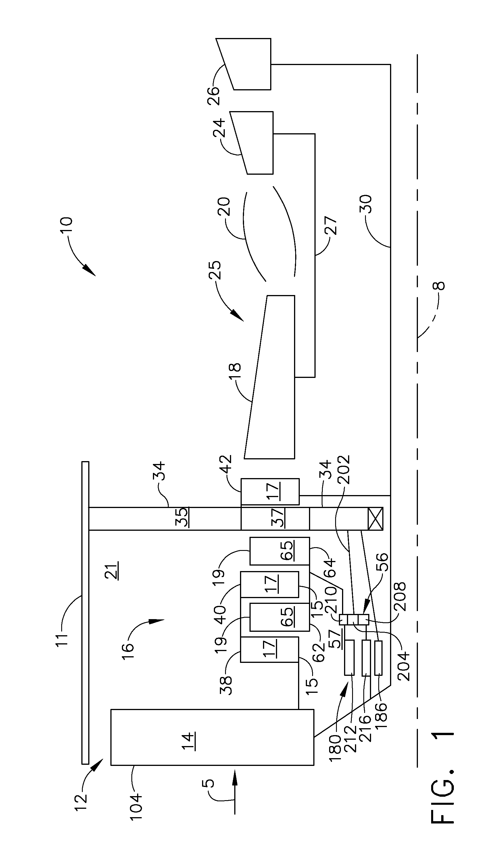
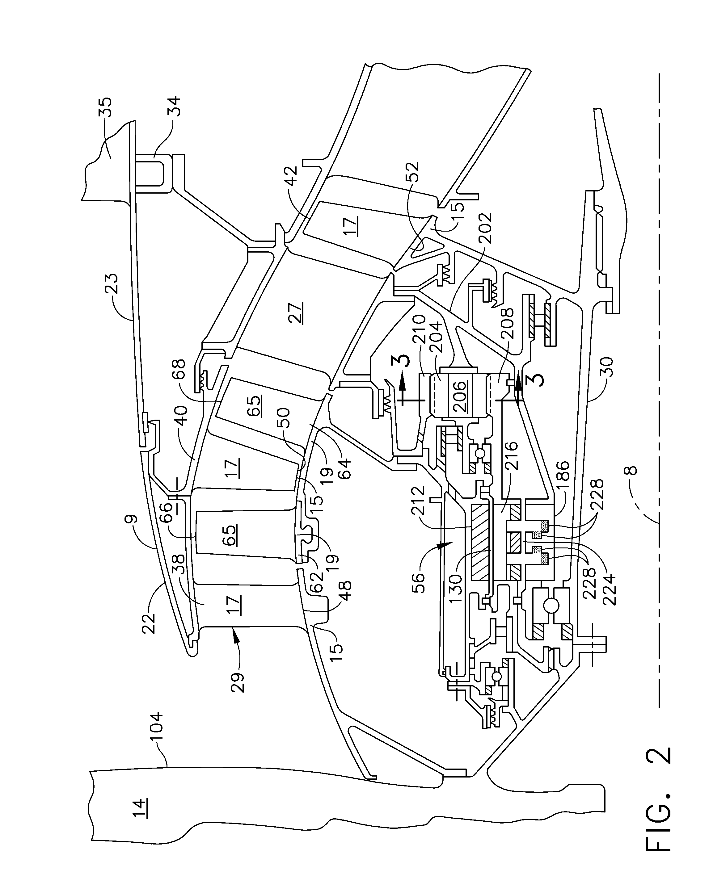
[0031]Diagrammatically illustrated in FIGS. 1 and 2 is an exemplary turbofan gas turbine engine 10 circumscribed about an engine centerline 8 and having a fan section 12 which receives inlet airflow of ambient air 5. The fan section 12 includes a single fan stage 104 of fan blades 14. Downstream of the fan section 12 is a counter-rotatable booster 16 with counter-rotatable first and second sets of booster stages 15, 19. The first set of booster stages 15 includes first, third, and fifth booster stages 38, 40, 42 of rotatable booster blades 17. The second set of booster stages 19 includes counter-rotatable second and fourth booster stages 62, 64 with counter-rotatable booster blades 65. One of the first and second sets of booster stages 15, 19 is rotatable in a clockwise direction about the engine centerline 8 and another of the first and second sets of booster stages 15, 19 is rotatable in a counter-clockwise direction about the engine centerline 8. Thus, the first and second sets o...


PUM


Abstract

An aircraft gas turbine engine includes a counter-rotatable generator driven by a turbine includes a generator stator and counter-rotatable radially inner pole and outer magnet rotors. A gearbox may be used for counter-rotating the pole and magnet rotors. Counter-rotatable first and second sets of booster stages may be co-rotatable with corresponding ones of the pole and magnet rotors. The generator and the gearbox may be disposed within a booster cavity or a tail cone of the engine. The magnet rotor, the pole rotor, and the stator may be concentric. A particular embodiment of generator includes the magnet rotor encircling the pole rotor, the pole rotor encircling the stator, a rotor air gap between the magnet and pole rotors, and a transformer air gap between the pole rotor and the stator. The counter-rotatable generator may be driven directly by a counter-rotatable turbine.

Description

BACKGROUND OF THE INVENTION[0001]1. Field of the Invention[0002]The invention relates to aircraft gas turbine engine electrical generators and, more particularly, to aircraft gas turbine engine electrical generators with counter-rotatable rotors.[0003]2. Description of Related Art[0004]An aircraft gas turbine engine of the turbofan type generally includes a forward fan and booster compressor, a middle core engine, and an aft low pressure power turbine. The core engine includes a high pressure compressor, a combustor, and a high pressure turbine in a serial flow relationship. The high pressure compressor and high pressure turbine of the core engine are interconnected by a high pressure shaft. The high pressure compressor, turbine, and shaft essentially form the high pressure rotor or spool. The high pressure compressor is rotatably driven to compress air entering the core engine to a relatively high pressure. This high pressure air is then mixed with fuel in the combustor and ignited...

Claims


Application Information

Patent Timeline
Patent Type & Authority Patents(United States)
IPC IPC(8): H02K16/02
CPCF01D15/10H02K16/02F02C7/32H02K7/1823
Inventor SCHILLING, JAN CHRISTOPHERTOOT, PETER DAVID
Owner GENERAL ELECTRIC CO
Why Eureka
Try Eureka