Microelectromechanical gyroscope with position control driving and method for controlling a microelectromechanical gyroscope

a microelectromechanical and gyroscope technology, applied in the direction of acceleration measurement using interia force, speed measurement using gyroscopic effects, electric/magnetic means, etc., can solve the problems of complex feedback driving circuit, ineffective, cumbersome and, in practice, costly

Active Publication Date: 2013-02-19
STMICROELECTRONICS SRL
View PDF16 Cites 63 Cited by
  • Summary
  • Abstract
  • Description
  • Claims
  • Application Information

AI Technical Summary

Benefits of technology

[0013]Embodiments of the present disclosure include a microelectromechanical gyroscope and a method for controlling a microelectromechanical gyroscope that are precise and reliable and are suitable for exploitation on a wide scale.

Problems solved by technology

The solution is simple, but also far from effective, because the resonance frequency is not known precisely on account of the non-eliminable spreads in semiconductor-micromachining processes.
For this reason, currently available feedback driving circuits are complex to produce, cumbersome and, in practice, costly.

Method used


Image

  • Microelectromechanical gyroscope with position control driving and method for controlling a microelectromechanical gyroscope
  • Microelectromechanical gyroscope with position control driving and method for controlling a microelectromechanical gyroscope
  • Microelectromechanical gyroscope with position control driving and method for controlling a microelectromechanical gyroscope

Examples


Embodiment Construction

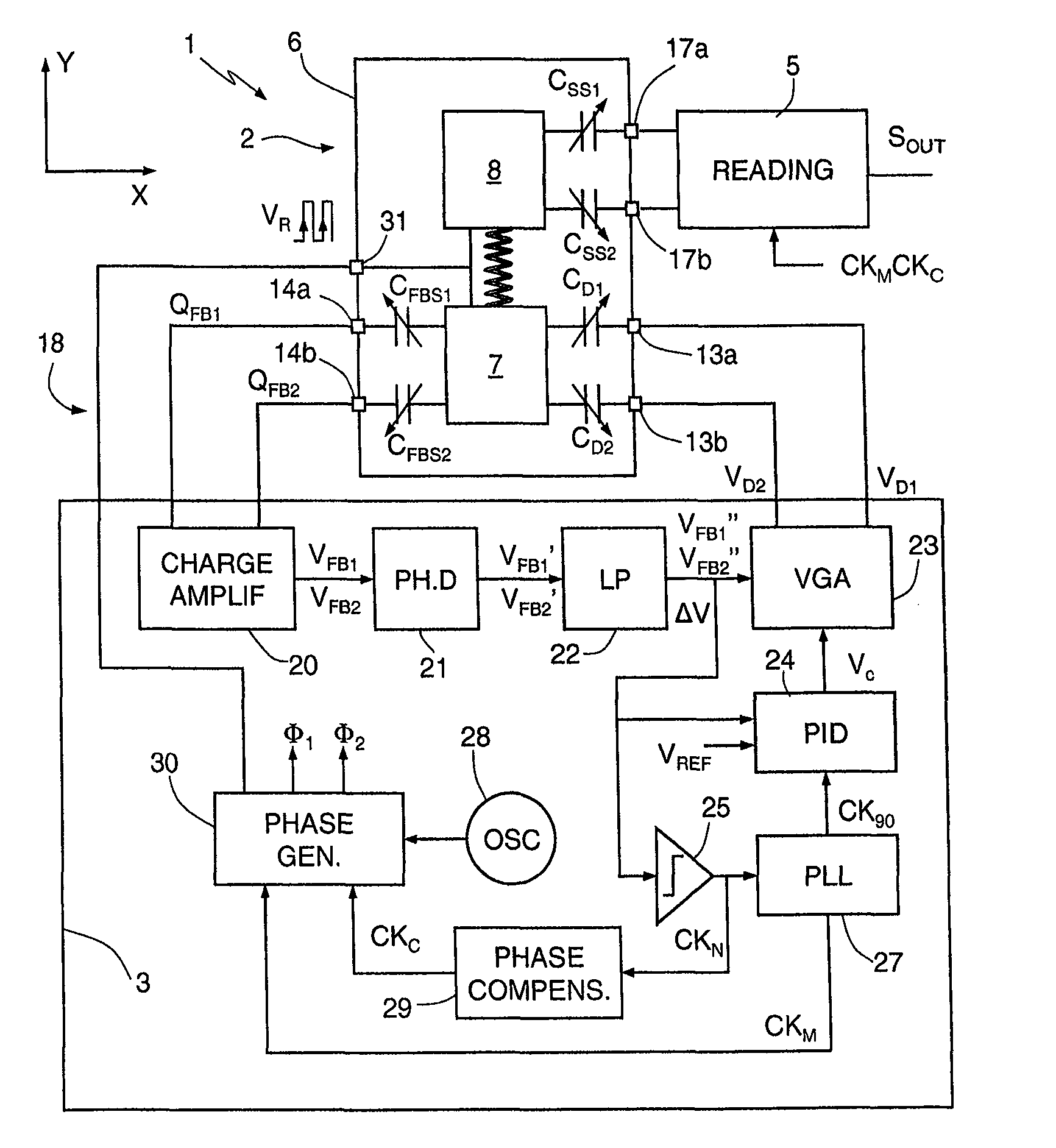
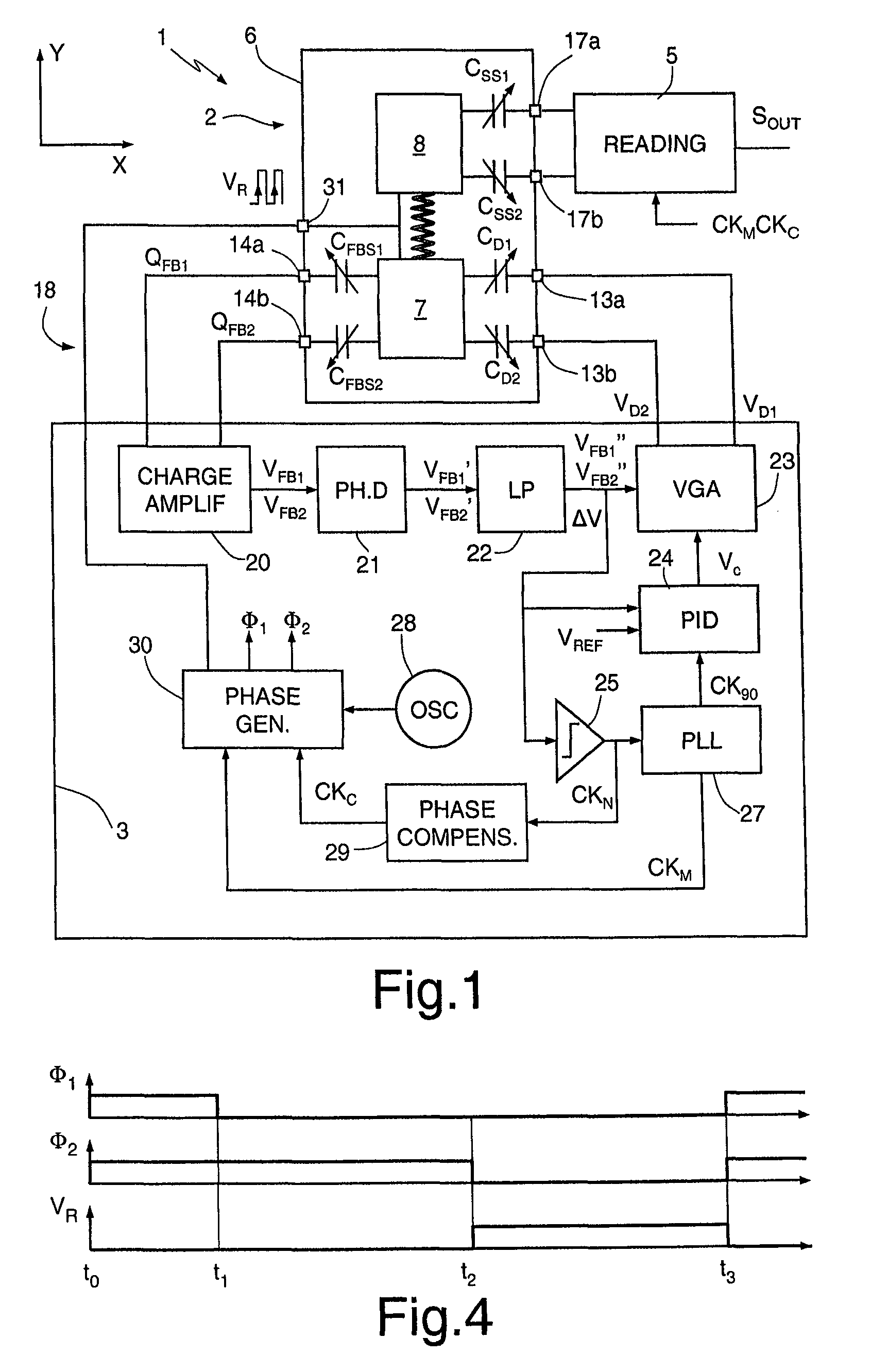
[0028]FIG. 1 shows as a whole a microelectromechanical gyroscope 1, which comprises a microstructure 2, made of semiconductor material, a driving device 3, and a reading device 5.

[0029]The microstructure 2 is made of semiconductor material and comprises a fixed structure 6, a driving mass 7, and at least one sensing mass 8. For simplicity, in the embodiment illustrated herein, reference will be made to the case of a uniaxial gyroscope, in which a single sensing mass 8 is present. What is described hereinafter applies, however, also to the case of multiaxial gyroscopes, which comprise two or more sensing masses, for detecting rotations according to respective independent axes.

[0030]The driving mass 7 is elastically constrained to the fixed structure 6 so as to be able to oscillate about a rest position according to one, translatory or rotary, degree of freedom. The sensing mass 8 is mechanically coupled to the driving mass 7 so as to be drawn in motion according to the degree of free...


PUM


Abstract

A MEMS gyroscope includes: a microstructure having a fixed structure, a driving mass, movable with respect to the fixed structure according to a driving axis, and a sensing mass, mechanically coupled to the driving mass so as to be drawn in motion according to the driving axis and movable with respect to the driving mass according to a sensing axis, in response to rotations of the microstructure; and a driving device, for keeping the driving mass in oscillation with a driving frequency. The driving device includes a discrete-time sensing interface, for detecting a position of the driving mass with respect to the driving axis and a control stage for controlling the driving frequency on the basis of the position of the driving mass.

Description

BACKGROUND[0001]1. Technical Field[0002]The present disclosure relates to a microelectromechanical gyroscope with position-control driving and to a method for controlling a microelectromechanical gyroscope.[0003]2. Description of the Related Art[0004]As is known, the use of microelectromechanical systems (MEMS) has become increasingly widespread in various fields of technology and has yielded encouraging results especially in the construction of inertial sensors, microintegrated gyroscopes, and electromechanical oscillators for a wide range of applications.[0005]MEMS of this type are usually based upon microelectromechanical structures comprising at least one movable mass connected to a fixed body (stator) through springs and movable with respect to the stator according to pre-determined degrees of freedom. The movable mass is moreover coupled to the fixed body via capacitive structures (capacitors). The movement of the movable mass with respect to the fixed body, for example on acc...

Claims


Application Information

Patent Timeline
Patent Type & Authority Patents(United States)
IPC IPC(8): G01C19/56
CPCG01C19/5726G01C19/56G01C19/5762H03F3/70
Inventor PRANDI, LUCIANOCAMINADA, CARLO
Owner STMICROELECTRONICS SRL
Why Eureka
Try Eureka