Multistage compressor installation

a compressor and installation technology, applied in the direction of machines/engines, liquid fuel engines, positive displacement liquid engines, etc., can solve the problems of pressure drop, pressure drop, pressure drop, etc., and achieve the effect of inhibiting pressure drop

Inactive Publication Date: 2013-02-19
PRAXAIR TECH INC
View PDF13 Cites 13 Cited by
  • Summary
  • Abstract
  • Description
  • Claims
  • Application Information

AI Technical Summary

Benefits of technology

[0008]The present invention, in one aspect, provides a multistage compressor installation that comprises two compression stages to compress a gas and an intercooler positioned between the two compression stages to remove heat of compression from the gas between the two compression stages. Each of the two compression stages comprise a centrifugal compressor and a driver configured to independently drive the centrifugal compressor of each of the two compression stages, the centrifugal compressor having an inlet surrounded by a volute and the volute having an outlet oriented so as to discharge compressed gas at right angles to the inlet. An inlet conduit connects the outlet of one of the two compression stages to the intercooler and an outlet conduit connects the intercooler to the inlet of the other of the two compression stages. The outlet of the one of the two compression stages is located substantially opposite to the inlet of the other of the two compression stages such that the inlet conduit and the outlet conduit are in an in-line relationship to inhibit pressure drop in the inlet conduit and the outlet conduit. Further, each of the inlet conduit and the outlet conduit is provided with tapered transition sections of ever increasing transverse cross-sectional area in the inlet conduit and ever decreasing transverse cross-sectional area in the outlet conduit such that flow velocity is gradually decreased in the inlet conduit and gradually increased in the outlet conduit to further inhibit pressure drops at connections between the inlet conduit and the intercooler and the outlet conduit and the intercooler.
[0011]Any of foregoing arrangements can be used without the tapered transition sections connecting the compression stages to the intercoolers. However, each of the pairs of conduits can consist of an inlet conduit connected to the outlet of the preceding stage and an outlet conduit connected to the inlet of the following stage. The inlet conduit and the outlet conduit can be provided with tapered transition sections of ever increasing transverse cross-sectional area in the inlet conduit and ever decreasing transverse cross-sectional area in the outlet conduit such that flow velocity is gradually decreased in the inlet conduit and gradually increased in the outlet conduit to further inhibit pressure drops at connections between the inlet conduit and the intercooler and the outlet conduit and the intercooler.

Problems solved by technology

The disadvantage of such arrangement is that since the compression stages are arranged around the bull gear, the piping or conduits connecting the stages to the intercoolers can become quite convoluted.
Each bend in the conduits results in a pressure drop due to turbulence induced in the flow by the change in direction of the gas within the bend.
This rapid increase in flow area also results in a pressure drop due to the resulting turbulence that is induced into the flow.
Also, mal-distributions in flow can occur in the intercooler such that not all of the heat exchange passages are utilized effectively.
Another disadvantage of the arrangement discussed above is that there are irreversible heat loses in gearboxes used in housing the bull gear and pinions.
Further, since the torque is transmitted in a geared arrangement, there are certain mechanical requirements for the size of gear teeth resulting in limitations in the size of the pinions and therefore, speed that can be induced in each of the compression stages.
However, in this patent application, there is no appreciation of the pressure drops that can be induced due to the connection of the intercoolers with the compression stages.

Method used


Image

  • Multistage compressor installation
  • Multistage compressor installation
  • Multistage compressor installation

Examples


Embodiment Construction

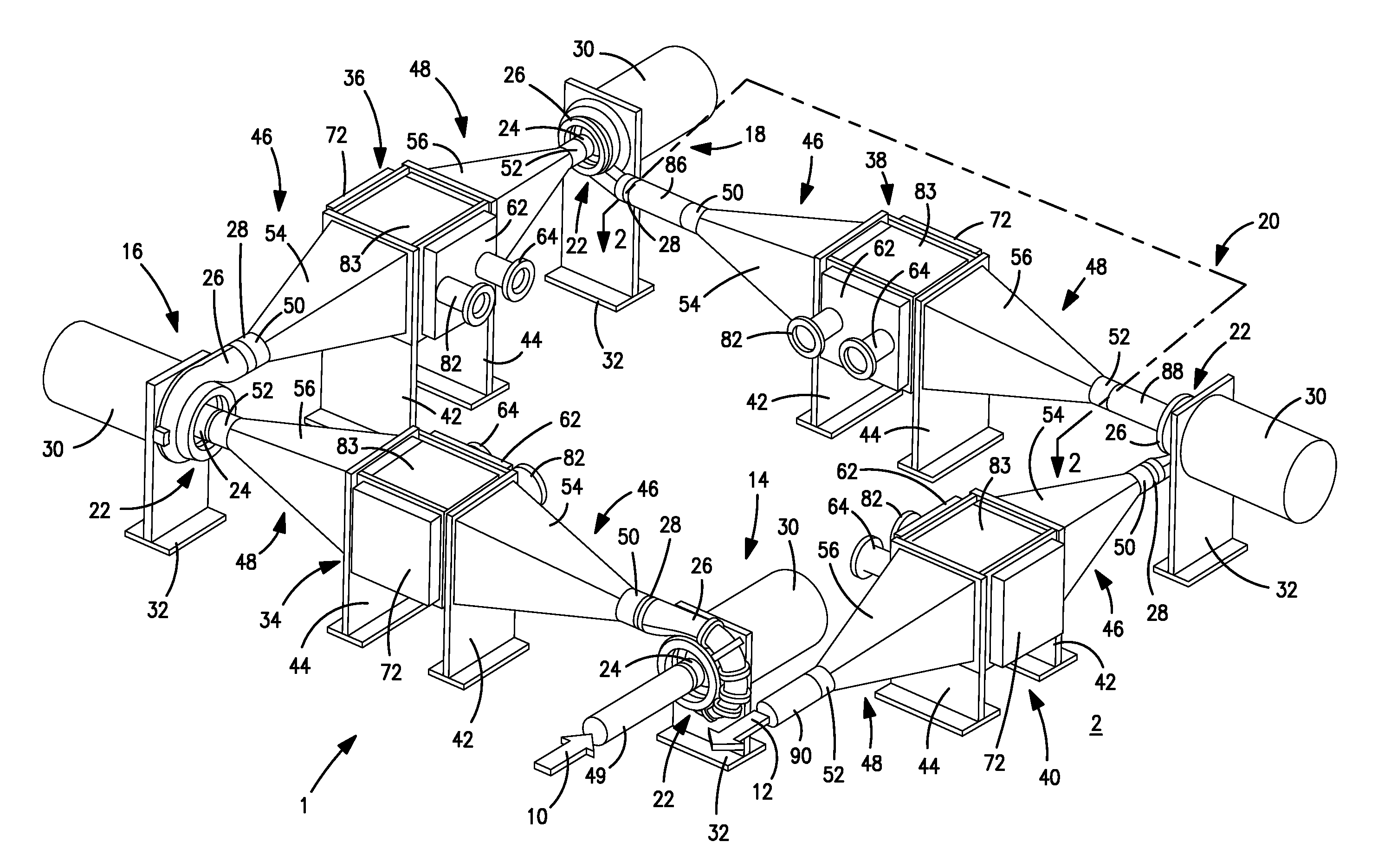
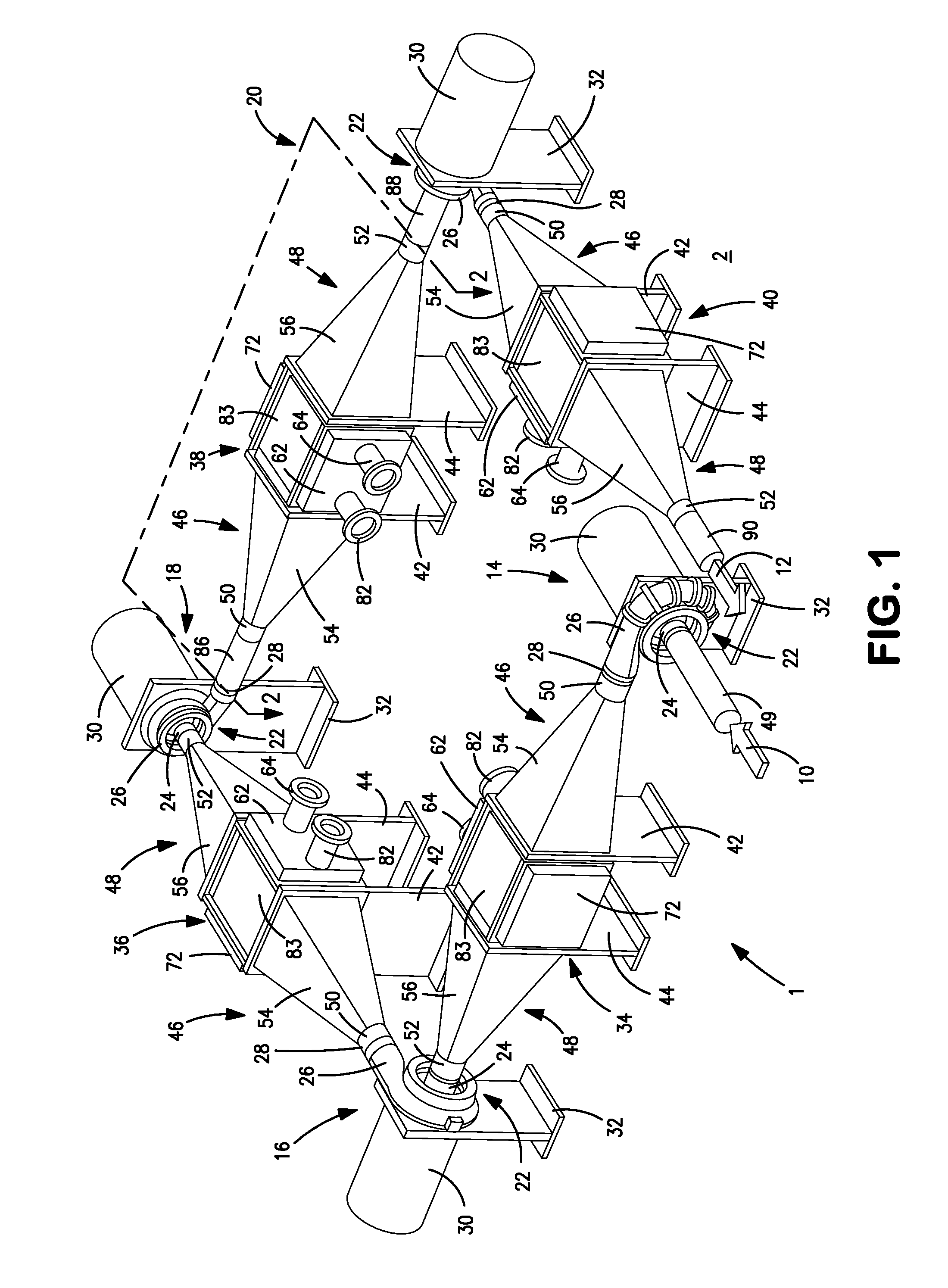
[0022]With reference to FIG. 1, a compressor arrangement 1 in accordance with the present invention is illustrated that is designed to compress a gas stream 10 and thereby produce a compressed gas stream 12. Gas stream 10 is compressed in four compression stages 14, 16, 18 and 20 in the production of compressed gas stream 12.

[0023]Each of the four compression stages 14, 16, 18 and 20 is provided with a centrifugal compressor 22 of known design having an inlet 24, a volute 26 and an outlet 28. Each compressor 22 may be different from one another in that they may each incorporate a design that is specifically configured to produce the desired pressure rise and an aerodynamic effect to achieve the maximum efficiency in a manner well known in the art. For example, each subsequent stage may actually be physically smaller due to the increase in the fluid density. As illustrated, each outlet 28 discharges compressed gas to the next succeeding stage at right angles to the inlet. For example...


PUM


Abstract

A multistage compressor installation in which compression stages utilizing centrifugal compressors are independently driven by drivers that can be electric motors configured to be controlled by a speed controller. Intercoolers are located between stages to remove the heat of compression and the stages are connected such that outlets are located opposite to inlets of the compressors and conduits connecting the intercoolers to the stages are in an in-line relationship to inhibit the formation of pressure drops between stages. The conduits connecting the stages incorporate tapered transition sections configured such that flow velocity gradually decreases towards the intercooler and gradually increases from the intercooler to the next succeeding compression stage to further inhibit pressure drops.

Description

FIELD OF THE INVENTION[0001]The present invention relates to a multistage compressor installation in which independently driven compression stages utilizing centrifugal compressors with intercoolers connected such that outlets are located opposite to inlets of the compressors and conduits connecting the intercoolers to the stages are in an in-line relationship to inhibit the formation of pressure drops between stages. More particularly, the present invention relates to such a compressor installation in which the conduits incorporate tapered transition sections configured such that flow velocity gradually decreases towards the intercooler and gradually increases from the intercooler to the next succeeding compression stage.BACKGROUND OF THE INVENTION[0002]Gases are compressed in many different types of industrial facilities and for a variety of purposes. For example, air is compressed, cooled and introduced into one or more distillation columns in an air separation plant. In a liquef...

Claims


Application Information

Patent Timeline
Patent Type & Authority Patents(United States)
IPC IPC(8): F04B25/00
CPCF04D25/16F04D27/0261F04D29/5826F05B2260/211Y02B30/70F04B25/00
Inventor BAKER, ROBERT LEROYGOODBAND, JEFFREY CHARLESJIBB, RICHARD JOHNROYAL, JOHN HENRI
Owner PRAXAIR TECH INC
Why Eureka
Try Eureka