Coupled electron shuttle providing electrical rectification

a technology of electron shuttle and electrical rectification, which is applied in the structure of radiating elements, resonance antennas, transmission, etc., can solve the problems of limited use of rectennas, lost power in the junction during the rectification process, and inability to extract power from low power density signals. , to achieve the effect of improving the design of the rectenna and low energy loss

Active Publication Date: 2013-02-19
WISCONSIN ALUMNI RES FOUND
View PDF7 Cites 4 Cited by
  • Summary
  • Abstract
  • Description
  • Claims
  • Application Information

AI Technical Summary

Benefits of technology

[0011]The present invention provides a rectifier using an electron shuttle that operates by transferring electrons between two terminals in vibratory mode which may be asymmetrical under certain operating conditions to rectify current. The potentially high-speed operation of this rectifier and low energy loss may permit improved rectenna design.
[0013]It is thus a feature of at least one embodiment of the invention to provide a new rectenna design having substantially improved performance particularly for low power density signals.
[0017]It is thus a feature of at least one embodiment of the invention to provide a simple method of producing the necessary electrically isolated elements using standard integrated circuit techniques and materials.
[0026]It is thus a feature of at least one embodiment of the invention to provide a simple and flexible way of eliminating inefficient modes of operation, for example, of frequencies which cause reverse current flow.

Problems solved by technology

A limitation in the use of rectennas, particularly for low power density radiation, comes from the rectifying element necessary to convert an electromagnetic signal to useful power.
Standard junction semiconductors, such as pn diodes, may be used for rectification but are relatively inefficient and have high forward bias voltages resulting in lost power in the junction during the rectification process.
Such high forward bias values can also make it impractical to extract power from low power density signals where these voltages are not readily obtained at the antenna output.

Method used


Image

  • Coupled electron shuttle providing electrical rectification
  • Coupled electron shuttle providing electrical rectification
  • Coupled electron shuttle providing electrical rectification

Examples


Embodiment Construction

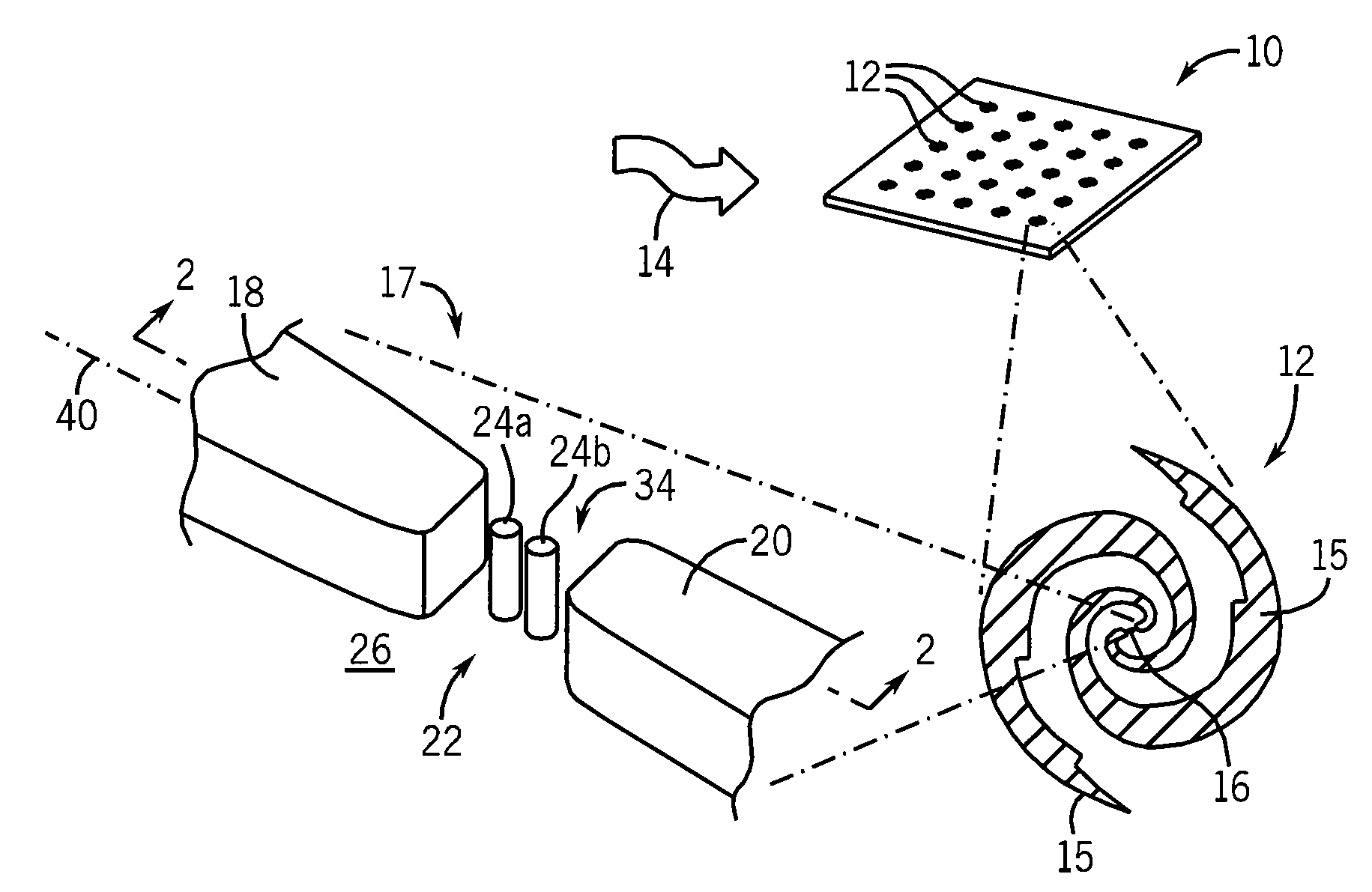
[0035]Referring now toFIG. 1, antenna array 10 of the present invention may provide for multiple antenna elements 12 designed to receive electromagnetic radiation 14. The multiple antenna elements 12 maybe electrically interconnected in series or in parallel to provide for desired power voltage and current as will be described below.

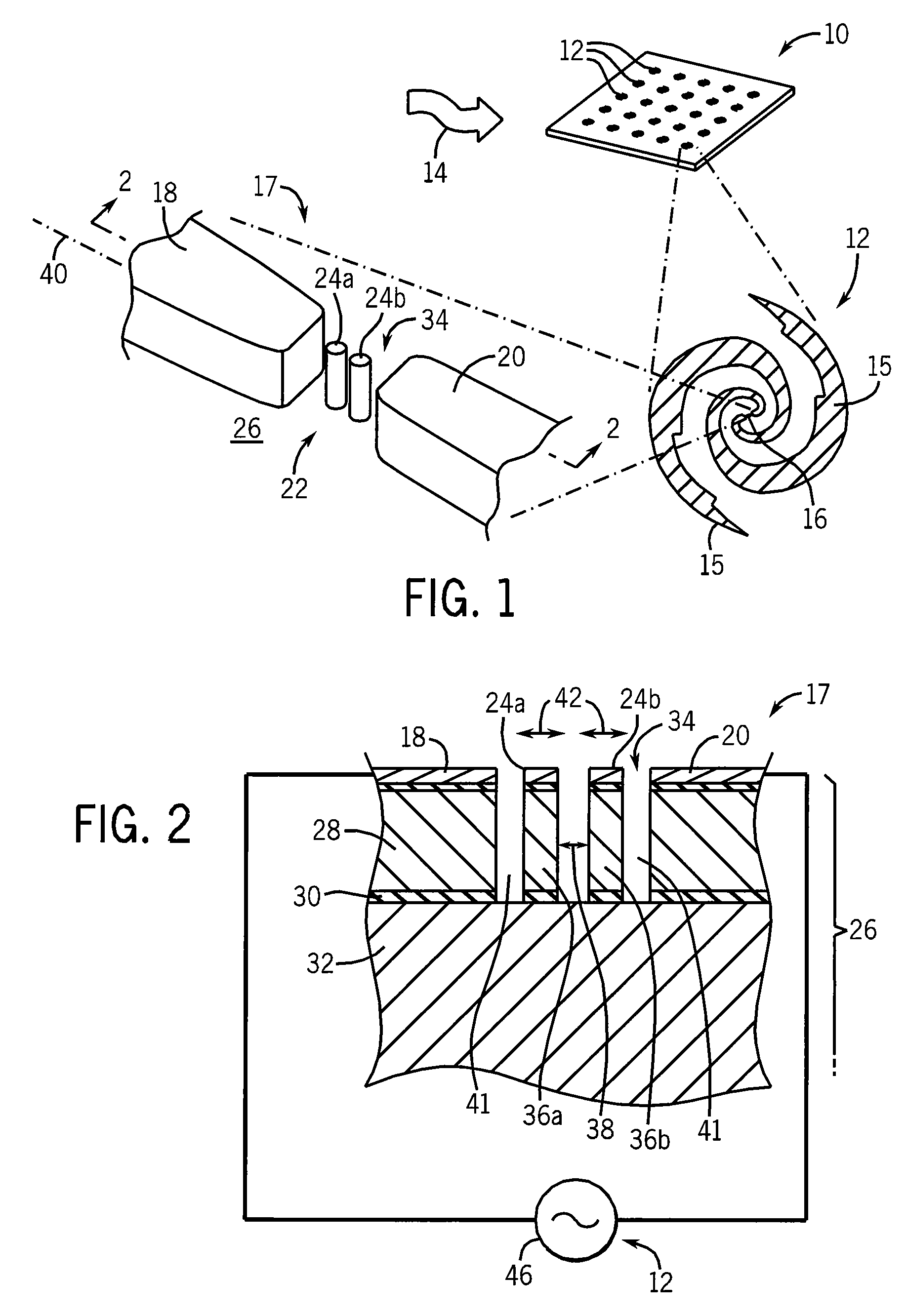
[0036]Each antenna element 12 may, for example, be a dipole providing for a pair of arms 15, here shown in a spiral configuration, for broadband frequency sensitivity. The arms 15 may connect to a rectification element 16 for extracting power from the electromagnetic radiation 14 received by the antenna element 12. The rectification element 16 may be an individual rectifier or a full wave bridge of a type understood in the art comprised of one or more rectifiers 17.

[0037]Referring also to FIG. 2, each rectifier 17 may include a first and second conductor 18 and 20 opposed across a gap 22 containing a first and second elastically mounted conducting elemen...


PUM


Abstract

A nanoscale electron shuttle with two elastically mounted conductors positioned within a gap between conductors produces asymmetrical electron conduction between the conductors when the conductors receive an AC signal to provide for rectification, detection and / or power harvesting.

Description

STATEMENT REGARDING FEDERALLY SPONSORED RESEARCH OR DEVELOPMENT[0001]This invention was made with United States government support awarded by the following agencies:[0002]NAVY N66001-07-1-2046[0003]USAF / AFOSR FA9550-08-0337[0004]The United States government has certain rights in this invention.CROSS-REFERENCE TO RELATED APPLICATIONS[0005]N / ABACKGROUND OF THE INVENTION[0006]The present invention relates to devices for converting free-space electromagnetic radiation to electrical power and in particular to a rectification element employing an electron shuttle useful for such a device.[0007]“Rectennas” are antennas that may receive radio signals and rectify them to generate electrical power for wireless power transfer. An example rectenna system was used in 1964 to power a tethered helicopter holding the rectenna and receiving a beam of microwave radiation from a ground-based microwave transmitter.[0008]Potential applications for rectennas include both large-scale power transfer applic...

Claims


Application Information

Patent Timeline
Patent Type & Authority Patents(United States)
IPC IPC(8): H01Q1/38
CPCH01Q1/248H01Q1/38H01Q9/27H01Q21/061H02M7/04
Inventor BLICK, ROBERT H.KIM, CHULKIPARK, JONGHOO
Owner WISCONSIN ALUMNI RES FOUND
Why Eureka
Try Eureka