Observation unit

a technology of observation unit and microscope, which is applied in the field of observation unit, can solve the problems of increasing the size of the incubator, affecting the sample, and killing the cell

Active Publication Date: 2013-02-19
PHC HLDG CORP
View PDF10 Cites 0 Cited by
  • Summary
  • Abstract
  • Description
  • Claims
  • Application Information

AI Technical Summary

Benefits of technology

[0011]In view of above described problem, an object of the present invention is to provide an observation unit which can be used in a storage such as an incubator, an isolator or the like without affecting a sample.
[0013]With the first observation unit, heat generated in the drive device is conducted to the ambient air to rise together with the air, and therefore, the heat of the drive device is hardly conducted to the placing table arranged at a position displaced from the drive device in the horizontal direction. Accordingly, the heat is hardly conducted to the sample placed on the placing table as well, resulting in inhibition of temperature increase of the sample. Therefore, it is possible to observe the sample without subjecting the sample to influence of heat such that cultivation of the sample is prevented, the sample is killed, or the like.
[0014]Further, the first observation unit can be easily made smaller, and therefore, it is possible to take the observation unit into or from the storage such as an incubator or the like, resulting in an increase in applicability.
[0023]With the fifth observation unit, it is possible to inhibit heat transfer from a heat source such as the drive device, the imaging system of the observation device or the like to the sample by moving the placing table to the separated position at the time other than observation.
[0025]With the sixth observation unit, even in the case where the placing table is replaced with one having a different shape, the center of the sample can be easily matched to the predetermined position.

Problems solved by technology

However, the sample such as a cell is sensitive to temperature change, and therefore, when taken out from the incubator, the sample can be affected such that the cell is killed, for example.
However, the incubator described above is provided with the observation device (the microscope unit) on the outside thereof, resulting in an increase in size of the incubator.
Also, the observation device is specific to the incubator described above, and therefore, it is difficult to apply the observation device to other incubators, resulting in low applicability.
However, if the conventional observation device is provided in the incubator without change, the observation device will be exposed to the environment in the incubator, and problems can be caused in an optical system or an imaging system of the observation device by moisture or the like.
However, when being operated, the drive motor generates a large amount of heat, and the heat can be conducted to the sample and affect the sample.

Method used


Image

  • Observation unit
  • Observation unit
  • Observation unit

Examples


Embodiment Construction

[0050]A preferred embodiment of the present invention is described in detail below with reference to the drawings.

[0051]1. Usage Configuration of Observation Unit

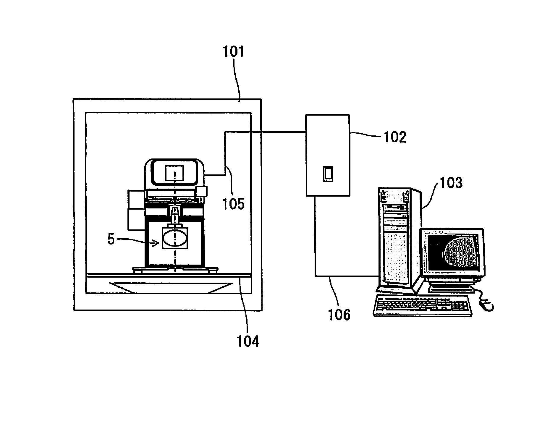
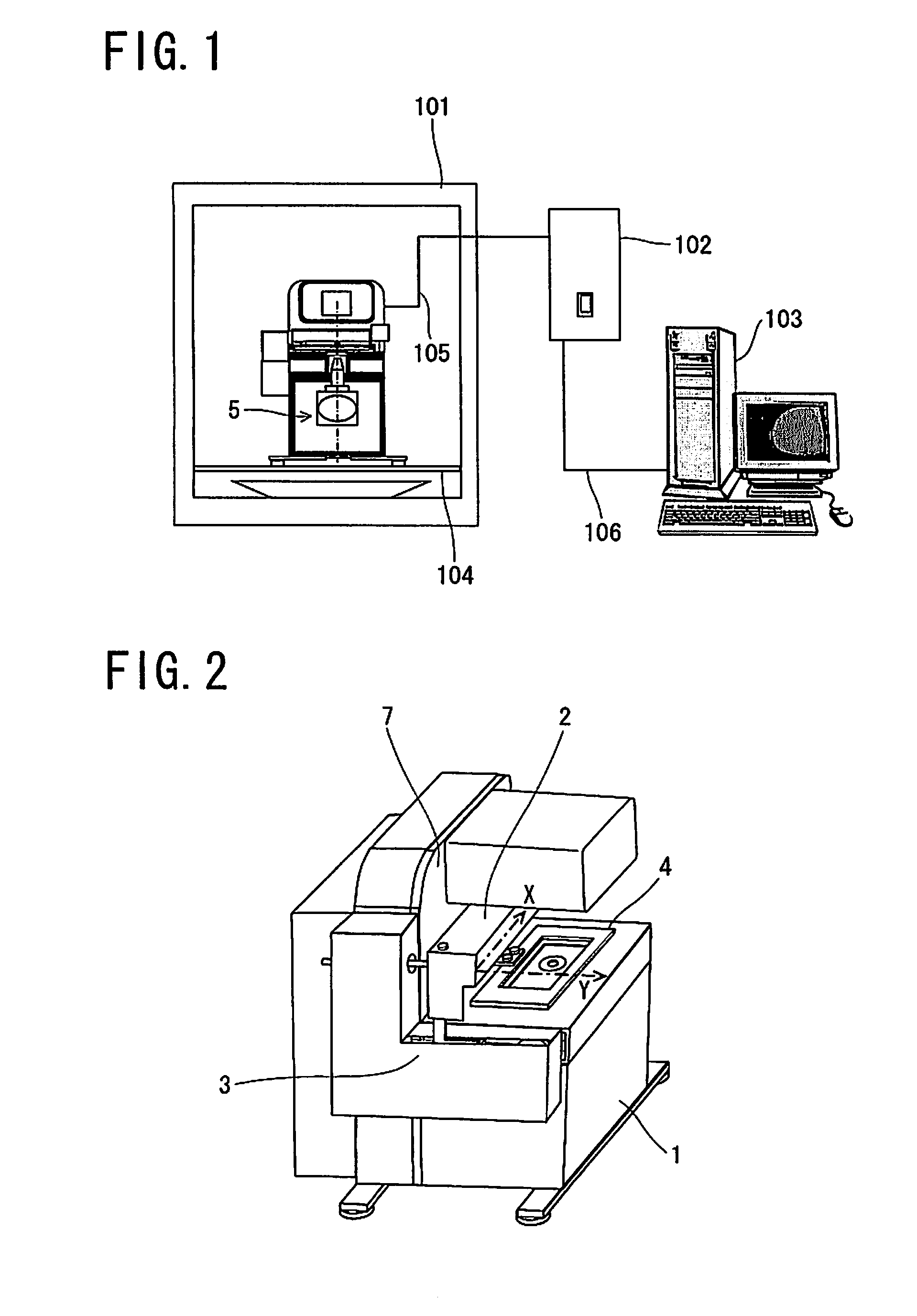
[0052]FIG. 1 is a view showing a usage configuration of an observation unit according to the embodiment of the present invention. As shown in FIG. 1, the observation unit can be taken into and from a storage 101 for culturing or storing a sample such as a cell or the like. The storage 101 includes an incubator, an isolator and the like. The storage 101 is provided therein with a shelf 104, and the observation unit is arranged on the shelf 104 to be used.

[0053]Although the storage 101 shown in FIG. 1 is merely provided with one shelf 104, the storage 101 can be provided therein with a plurality of shelves so that a plurality of fluid vessels containing the sample can be stored.

[0054]The observation unit is connected to a control device 102 installed outside the storage 101 via a cable 105. The control device 102 controls the...


PUM


Abstract

The observation unit according to the present invention comprises an observation device observing a sample, a placing table on which the sample is placed, a drive device moving the placing table to an observation position where the sample is observed by the observation device, and a casing sealing a first space extending in a vertical direction. The first space and the placing table are arranged so as to be displaced from each other in a horizontal direction, and the drive device is arranged in the first space.

Description

[0001]The application Number 2008-324661, upon which this patent application is based, is hereby incorporated by reference.BACKGROUND OF THE INVENTION[0002]1. Field of the Invention[0003]The present invention relates to observation units used in an incubator, an isolator or the like. The incubator controls a culture environment in which cells are cultured, and the isolator is a device which includes a sterile space for biological or chemical work.[0004]2. Description of Related Art[0005]Conventionally, an incubator has been used as a device for culturing a sample such as a cell. However, in a conventional incubator, it is necessary to take out the sample from the incubator in order to observe condition of the sample under culture. However, the sample such as a cell is sensitive to temperature change, and therefore, when taken out from the incubator, the sample can be affected such that the cell is killed, for example.[0006]In view of above problem, it has been proposed to provide th...

Claims


Application Information

Patent Timeline
Patent Type & Authority Patents(United States)
IPC IPC(8): G02B21/26
CPCC12M23/50C12M41/14C12M41/36
Inventor HOUJOU, MIKIOMURAKAMI, SEIJIASAI, YASUHIROYAMANAKA, YOSHITAROINOUE, TAKAHIRO
Owner PHC HLDG CORP
Why Eureka
Try Eureka