
Magnification-varying optical device

a technology of optical devices and magnification, which is applied in the direction of mountings, telescopes, instruments, etc., can solve the problems of poor operability, poor optical performance of conventional zoom binoculars, and inability to produce clear images, etc., and achieves good optical properties, simplified structural configuration, and improved optical performance.

Active Publication Date: 2013-02-19
KAMAKURA KOKI
View PDF18 Cites 0 Cited by
  • Summary
  • Abstract
  • Description
  • Claims
  • Application Information

AI Technical Summary

Benefits of technology

This solution optimizes optical properties by adjusting lenses within a predetermined range, enabling quick magnification changes and reducing production costs and weight, allowing for larger zoom binoculars with improved optical performance and practicality.

Problems solved by technology

Such conventional zoom binoculars are often inferior in optical performance due to their structures.
Specifically, they are apt to have darker images and smaller visual fields than scopes with a fixed magnification, or they are not able to produce clear images due to insufficient correction of optical aberration.
However, the complicated mechanism for moving lenses prohibits quick zooming operation between the extreme magnifications, which makes operability poor.
Besides, zoom binoculars require a number of lenses and complicated mechanisms for moving lenses, which makes resultant products more expensive and heavier than fixed magnification binoculars.
It is also difficult to place binoculars with a large objective aperture, which has excellent optical performance, into practical use.

Method used


Image

  • Magnification-varying optical device
  • Magnification-varying optical device
  • Magnification-varying optical device

Examples


Embodiment Construction

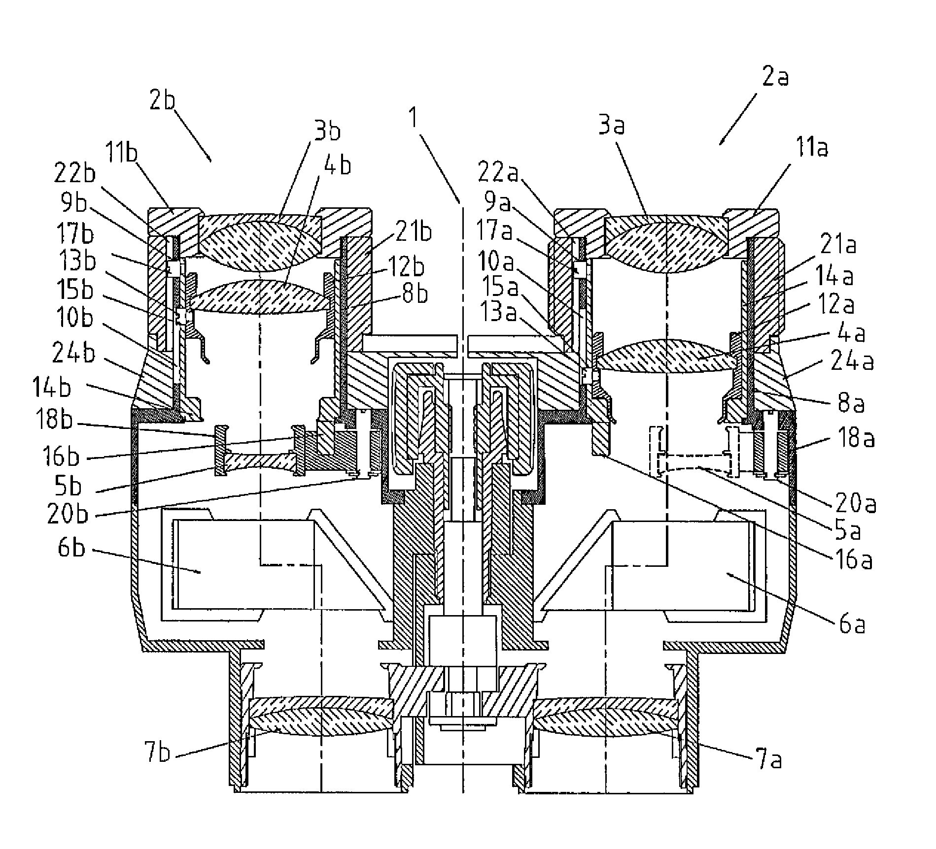
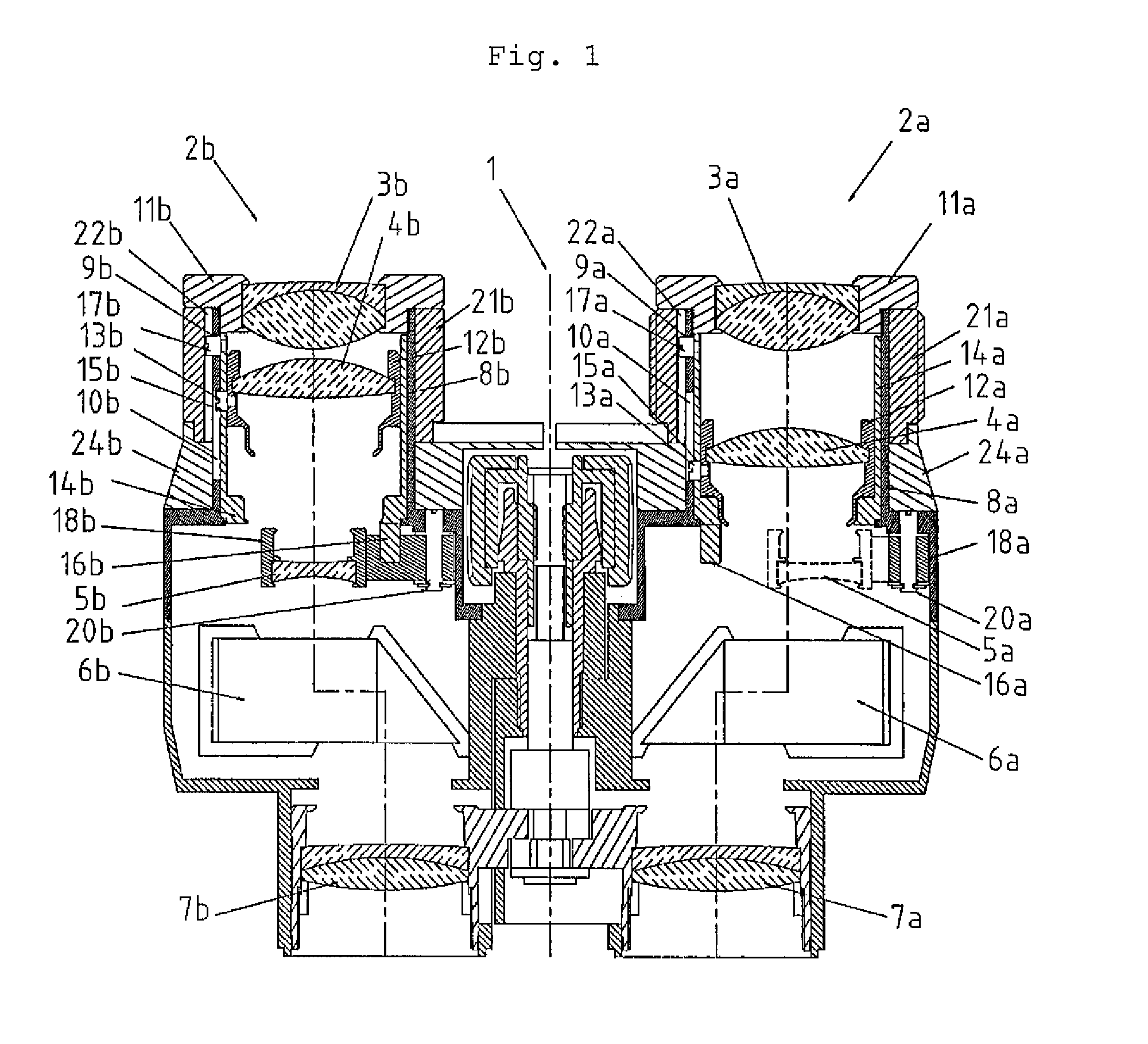
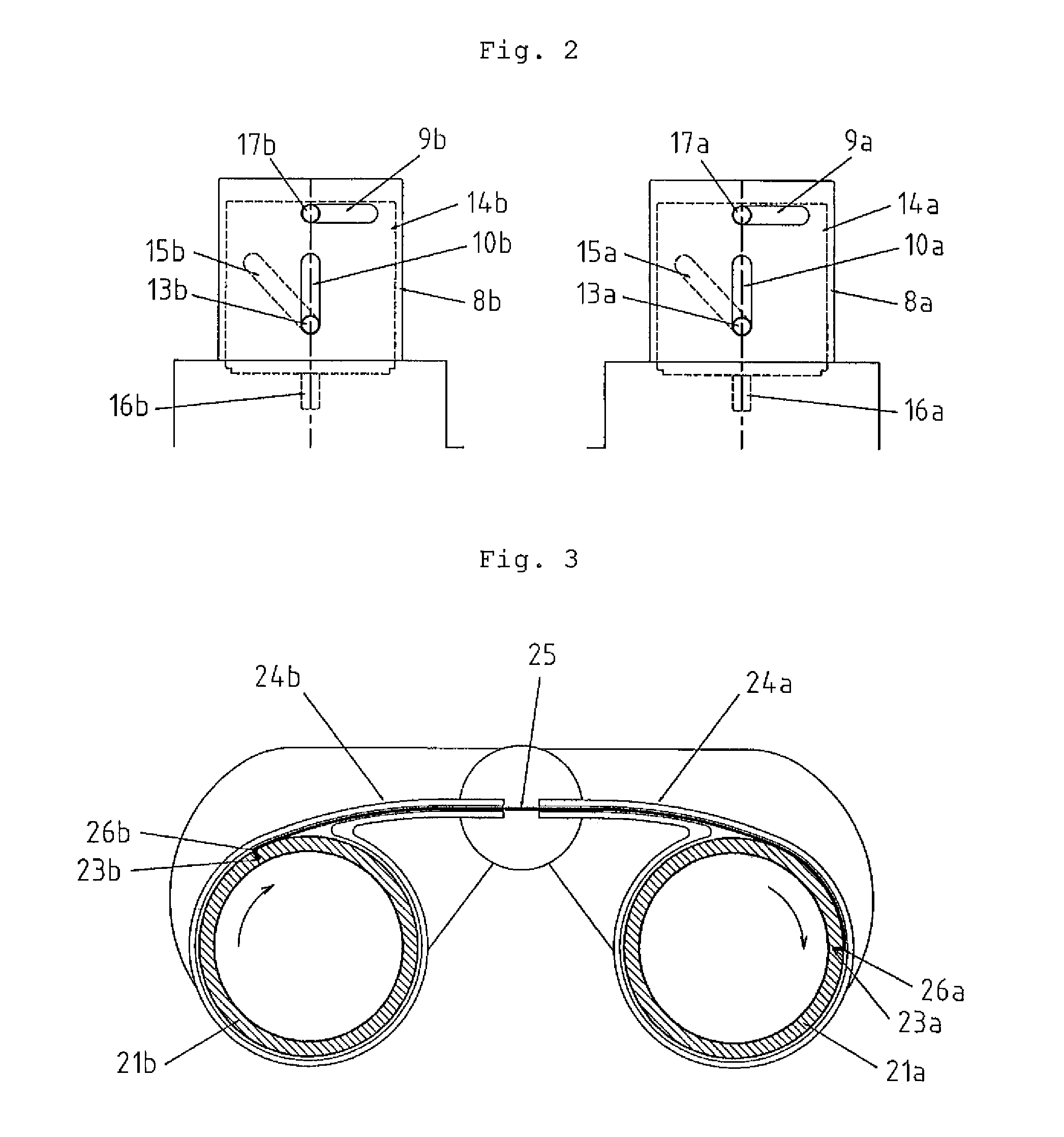
[0030]We will explain a pair of zoom binoculars, an example in which the magnification-varying optical device according to the present invention is embodied, referring to the attached figures.

[0031]FIG. 1 is a longitudinal sectional view of the pair of binoculars. Note that this figure is a sectional view to illustrate the present invention and it is not a view taken upon a single plane. The view of this figure has not only sections including optical axes and a central axis but also sections appropriate to showing principal parts of the binoculars.

[0032]In FIG. 1, reference numeral 1 denotes a central axis of the binoculars, 2a a right barrel for the right eye of a user, and 2b a left barrel for the left eye of the user. The right barrel shown in the figure is that in a state where the magnification is low, and the left barrel shown is that in a state where the magnification is high. In the figures other than FIG. 1 and the following description, members associated with the right ba...


PUM


Abstract

The invention relates to improving optical properties of optical instruments with variable magnification, such as zoom binoculars, reducing the weight thereof, and enabling the user to change magnifications quickly. The invention provides an optical instrument with a focal length-varying lens 4 disposed on the optical axis between an objective lens 7 and an eyepiece 3, further having an adjusting lens 5 for adjusting optical properties when the focal length-varying lens is in an area to provide high magnification. The adjusting lens is supported so that it is capable of moving between a location on the optical axis and a location off the path of light beams. Interlocked with a magnification-varying mechanism that controls the position of the focal length-varying lens, the adjusting lens is moved to the on-the-axis location when the focal length-varying lens is in an area to provide high magnification, and to the off-the-axis location when low magnification.

Description

TECHNICAL FIELD[0001]The present invention relates to a magnification-varying optical device applicable to so-called zoom binoculars or field spotting scopes.BACKGROUND ART[0002]Binoculars, as an example of optical instruments, are classified into binoculars with fixed magnification and binoculars with variable magnification or so-called zoom binoculars.[0003]Zoom binoculars are equipped with many lenses, compared with fixed magnification scopes, so as to have good optical performance irrespective of their varied magnifications, as disclosed in Patent Document 1. Also, zoom binoculars are provided with complicated mechanisms for moving lenses to vary the magnification without changing their focal point.[0004]Patent Document 1: JP H10-246858 ADISCLOSURE OF THE INVENTION[0005]Such conventional zoom binoculars are often inferior in optical performance due to their structures. Specifically, they are apt to have darker images and smaller visual fields than scopes with a fixed magnificati...

Claims


Application Information

Patent Timeline
Patent Type & Authority Patents(United States)
IPC IPC(8): G02B23/00
CPCG02B7/10G02B15/04G02B23/18G02B23/145
Inventor WATANABE, NAOMIMIYAJI, KAZUYA
Owner KAMAKURA KOKI
Learn More