Cut sight gauge

a sight gauge and cutting technology, applied in the field of cutting sight gauges, can solve the problems of not having a basic visual measurement gauge that allows the operator, and achieve the effect of reasonable manufacturing cos

Inactive Publication Date: 2013-02-26
DUNN WALTER
View PDF5 Cites 14 Cited by
  • Summary
  • Abstract
  • Description
  • Claims
  • Application Information

AI Technical Summary

Benefits of technology

[0016]The present invention provides a novel device that can be retrofit on existing corn crop production machines and provides an efficient and easy to use means of making measured height adjustments.
[0017]The unique innovation of the cut sight gauge is that the measuring and set up is performed from the safety of the operator's platform or cab. The contact to the machine by the ground personnel is eliminated.
[0018]The setup of the machine is accomplished in the matter of traveling a short distance at the beginning of each field. The area supervisor can determine the proper height from behind the machine at a safe distance and can signal the operator to adjust the cut sight to the optimum height required. Once the cut sight gauge is set the operator can maintain the specified uniform height at all times during the operating period.

Problems solved by technology

While the various prior art devices have provided for means of adjusting the height, none disclose a basic visual measurement gauge that allows the operator to set and monitor the height of the apparatus and to also make measured relative adjustments to the height.

Method used


Image

  • Cut sight gauge
  • Cut sight gauge
  • Cut sight gauge

Examples


Embodiment Construction

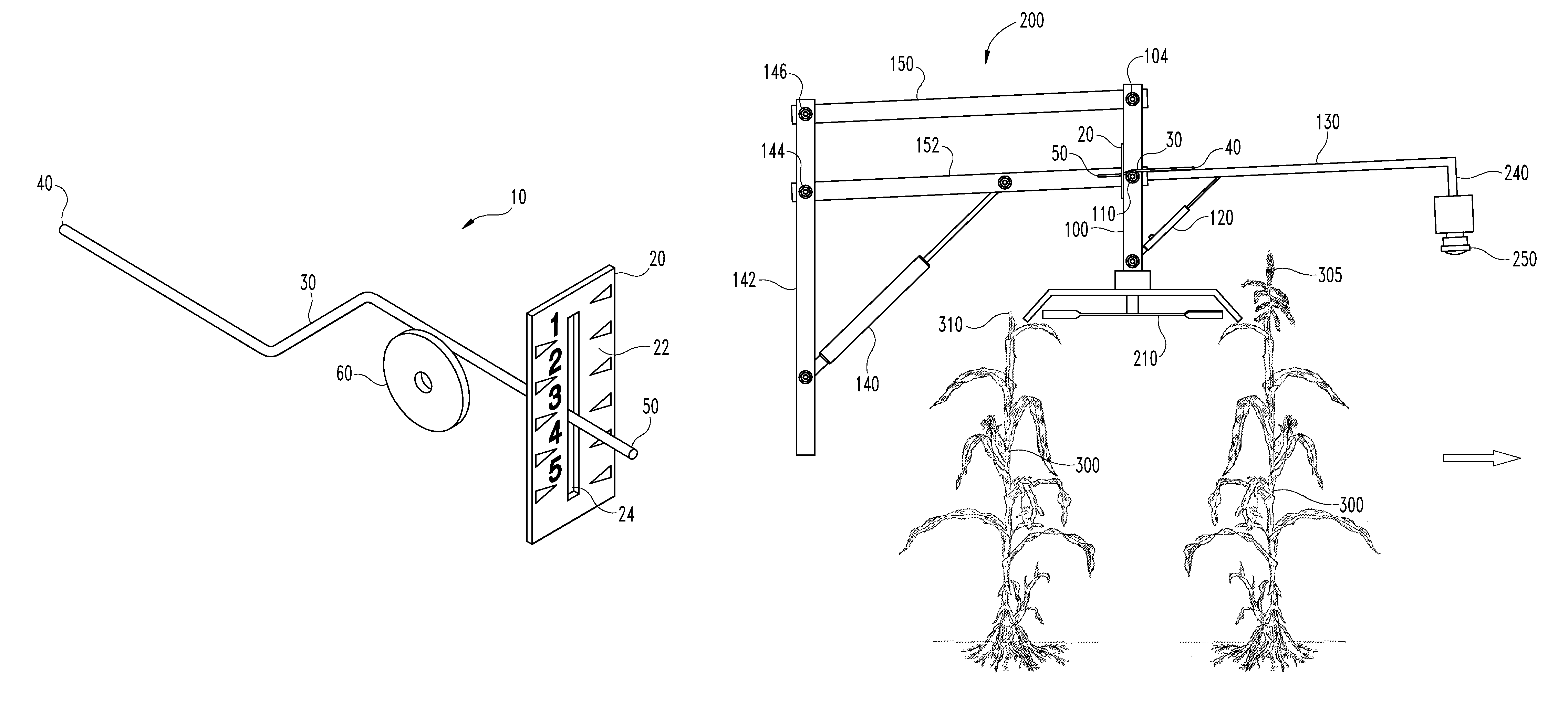
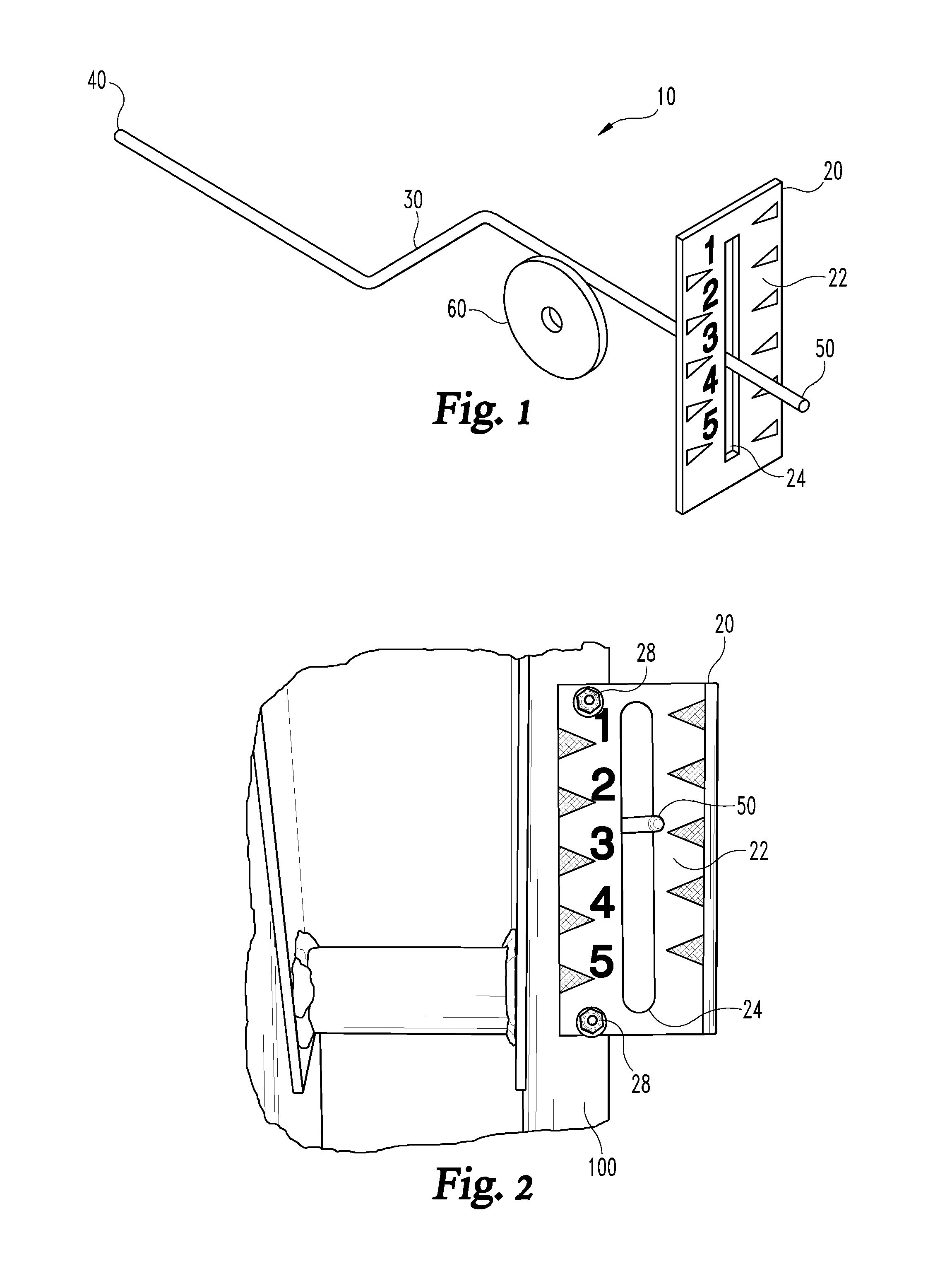
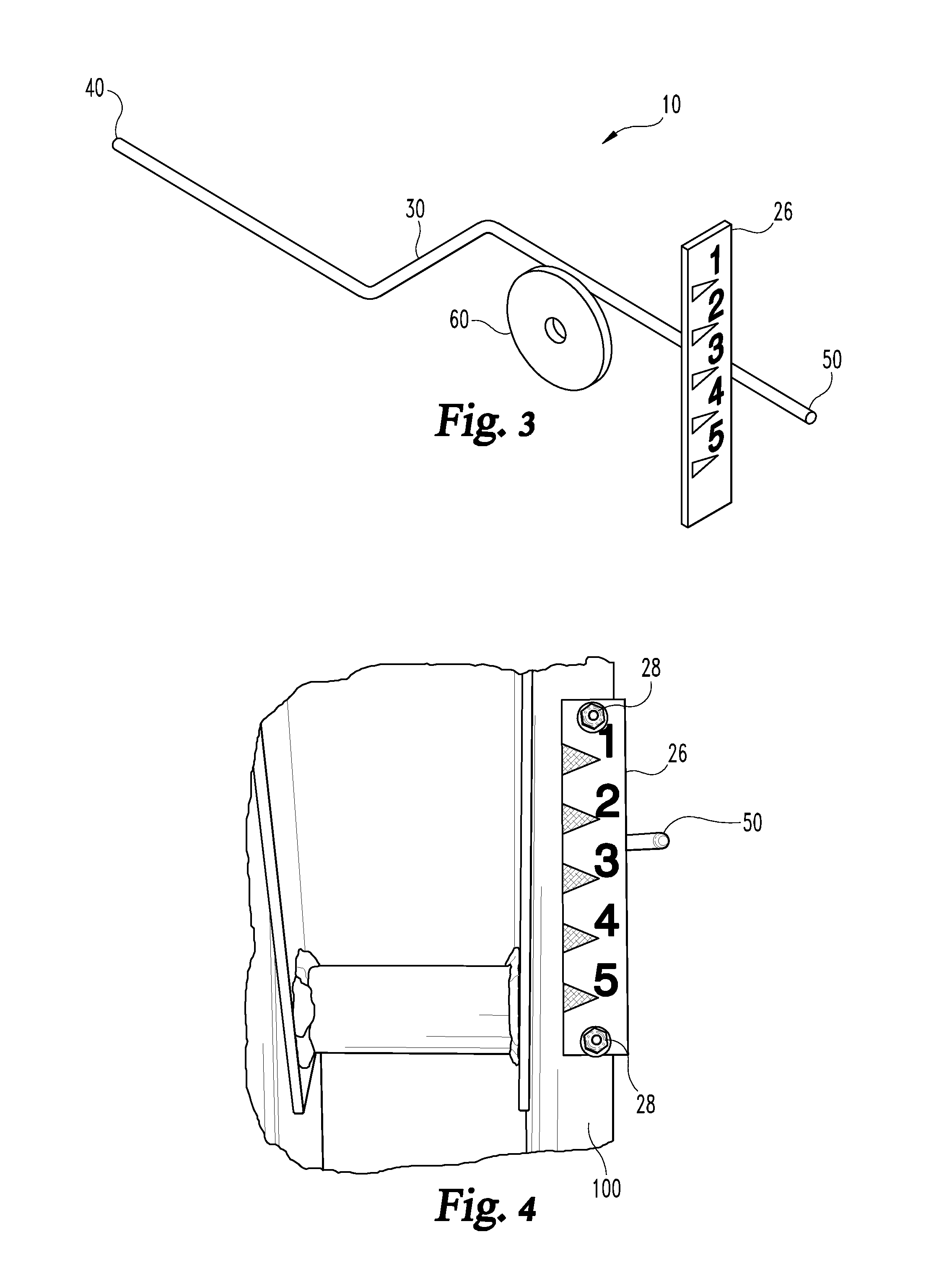
[0035]Referring now to the drawings and in particular to FIG. 1, wherein there is illustrated the cut sight gauge assembly 10, a detailed description of the invention is provided herein.

[0036]Shown in FIG. 1 is the cut sight gauge assembly 10 that includes a numbered face plate 20 and a pointer rod 30. In one embodiment of the numbered face plate 20, there is a front 22 and a slot 24. The pointer rod 30 has a forward tail 40, an indicator tip 50 and an attachment assembly 60, where in FIG. 1 the attachment assembly 60 is shown as a washer that is fixedly attached to the pointer rod 30. The indicator tip 50 is aligned to move along the length of the numbered face plate 20 so that the location of the indicator tip 50 relative to the numbered face plate 20 provides a measurement indicator of the position of the sensor mount bar 130, shown in FIGS. 5, 6 and 7. As shown in FIG. 1, the front 22 of the numbered face plate 20 may be marked by numbers and gradations. In one embodiment of the...


PUM


Abstract

A cut sight gauge for corn field production equipment used for detasseling operations where the cut sight gauge allows the operator to visually monitor the height of cutters and tassel pullers on corn crop cutting machines. The cut sight gauge ensures a uniform operating height of cut consistent with the optimum growing demands of the plants. The added safety advantage to the operator and the area supervisors who manage field operations are also a benefit for the field-specific set up applications as described herein.

Description

BACKGROUND OF THE INVENTION[0001]The present invention relates to the field of corn field production equipment used for detasseling operations. More specifically, the present invention is a cut sight gauge for providing an integrated means of monitoring the height of cutters and tassel pullers on corn crop cutting machines. The cut sight gauge ensures a uniform operating height of cut consistent with the optimum growing demands of the plants. The added safety advantage to the operator and the area supervisors who manage field operations are also a benefit for the field-specific set up applications as described herein.[0002]Corn field production typically requires the removal of tassels from corn stalks to facilitate desired pollination in fields planted with multiple seed types for hybrid production. A detasseling machine is used to cut off the tops of corn stalks in one operation that levels the heights of the top of the stalks and facilitates the later removal of tassels by anothe...

Claims


Application Information

Patent Timeline
Patent Type & Authority Patents(United States)
IPC IPC(8): A01D41/14
CPCA01D47/00
Inventor DUNN, WALTER
Owner DUNN WALTER
Why Eureka
Try Eureka