Joint for fluid container

a fluid container and joint technology, applied in the direction of liquid transfer devices, machines/engines, couplings, etc., can solve the problems of economic disadvantage of one way mode, and achieve the effects of convenient connection, quick connection, and avoid separation

Active Publication Date: 2013-02-26
TOKYO OHKA KOGYO CO LTD +1
View PDF11 Cites 15 Cited by
  • Summary
  • Abstract
  • Description
  • Claims
  • Application Information

AI Technical Summary

Benefits of technology

[0012]The container 7 according to Patent Document 1 includes the breakable seal 727. Accordingly, the probe 846 provided in the dispenser 8 breaks through the seal 727, thereby making it possible to insert the probe 846 into the void space 790 (see FIG. 6). However, there is a problem, at this time in that fracture pieces of the seal 727 may mix in the bag 720 through the void space 790 (see FIG. 5). Moreover, there has been concern regarding a case in which an operator can not properly break through the seal, causing clogging of the probe, thereby disabling the connection. It is possible to eliminate the aforementioned problem by achieving a joint structure by which the dispenser is connected to the container without the use of a breakable seal. In addition, it is more preferable if a one-touch connection to the container is made possible without threading to the dispenser.
[0050]The joint for a fluid container according to the present invention is configured such that the liquid pouring tube having the collar portion can be attached to the mouth portion of the outer container through the plug. This makes it possible to easily attach the liquid pouring tube independent of the force applied by the operator for adjustment. Moreover, the fluid container is configured such that the duct provided in the dispenser can be directly connected to the fluid passage of the liquid pouring tube, thereby making it possible to easily connect the dispenser to the container.

Problems solved by technology

Particularly, it is preferable to use the container in the one way mode in order not to affect the degree of purity of a high-purity chemical; however, the one way mode has an economic disadvantage.

Method used


Image

  • Joint for fluid container
  • Joint for fluid container
  • Joint for fluid container

Examples


Embodiment Construction

[0057]In the following, the most preferred embodiments of the present invention are described with reference to the drawings.

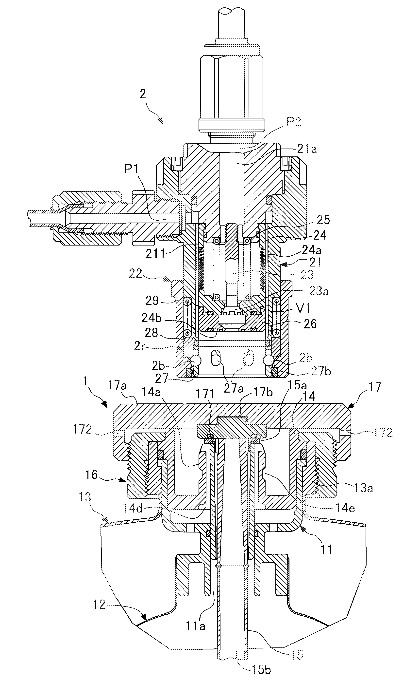
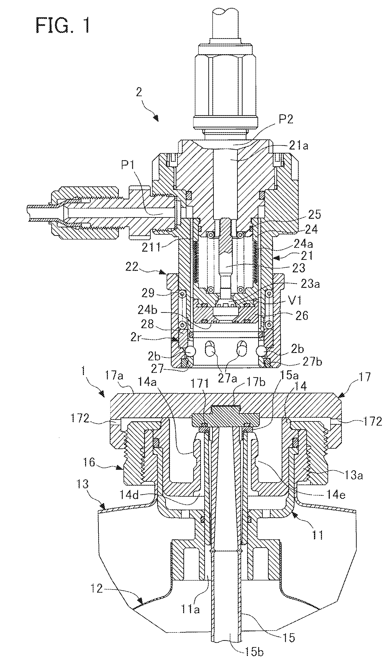
[0058]FIG. 1 is a longitudinal section representing an embodiment of a joint for a fluid container (hereinafter referred to as a container) of the present invention, showing a top end and a dispenser of the container. FIG. 2 is a cross-sectional exploded view of the top end of the joint for a container according to the embodiment. FIG. 3 is a cross-sectional exploded view of the joint for a container according to the embodiment, showing the top end and the dispenser of the container. FIG. 4 is a longitudinal section of the joint for a container according to the embodiment, showing an assembled container and dispenser.

[0059]First, a configuration of a container used in the present, invention is explained. In FIG. 1, a container 1 includes a flexible bag 12 and an outer container 13. The bag 12 has a neck portion 11 that is open for making it possible to pour li...


PUM


Abstract

A joint for duplex storage type fluid container that can attain secure fitting of a liquid discharge tube and can attain easy, secure connection of a passage for fluid emission disposed in a dispenser to the liquid discharge tube. There is provided a joint for fluid container comprising flexible bag (12) furnished with neck part (11) openable for permitting injection of liquid and comprising outside container (13) formed so as to support the neck part (11) by mouth part (13a) and accommodate the bag (12), which joint is so structured that liquid discharge tube (15) with collar part (15a) can be fitted through plug (14) to the mouth part (13a) of the outside container (13), and further so structured that flow channel (21a) fitted to dispenser (2) can be linked directly to fluid passage (15b) of the liquid discharge tube (15).

Description

CROSS-REFERENCE TO RELATED APPLICATIONS[0001]This application is the National Stage of International Application No. PCT / JP2006 / 322180, filed Nov. 7, 2006, which claims the benefit of Japanese Application No. 2006-023763, filed Jan. 31, 2006, the contents of both of which are incorporated by reference herein in their entirety.FIELD OF THE INVENTION[0002]The present invention relates to a joint for a container for storing, transporting and distributing fluids such as chemicals for the electronics industry. Specifically, the present invention relates to a joint structure of a container for draining fluids.BACKGROUND OF THE INVENTION[0003]For example, chemicals for the electronics industry such as photo-resist are stored in a chemical container for transport, and are delivered to a factory. Such a chemical container is used in a linking configuration by which the same container is repeatedly used, or in a one way configuration by which a new container is used each time. Particularly, i...

Claims


Application Information

Patent Timeline
Patent Type & Authority Patents(United States)
IPC IPC(8): F16K24/00
CPCB67D7/0261Y10T137/314Y10T137/86332Y10T137/87965B65D83/00F16L37/23
Inventor HASEGAWA, TORUTAKEDUTSUMI, TOSHIKIHASUNUMA, MASAHIRO
Owner TOKYO OHKA KOGYO CO LTD
Why Eureka
Try Eureka