Steering-force transmitting apparatus for vehicle
a transmission apparatus and steering force technology, applied in the direction of steering parts, power driven steering, vehicle components, etc., can solve the problems that the steering-force transmission apparatus equipped with the rotation transmission mechanism has difficulty in being installed on the vehicle, and achieve the effect of increasing the practicability of the steering-force transmission apparatus, reducing the cost of operation, and increasing the length
- Summary
- Abstract
- Description
- Claims
- Application Information
AI Technical Summary
Benefits of technology
Problems solved by technology
Method used
Image
Examples
first embodiment
1. Overall Construction of Steering System
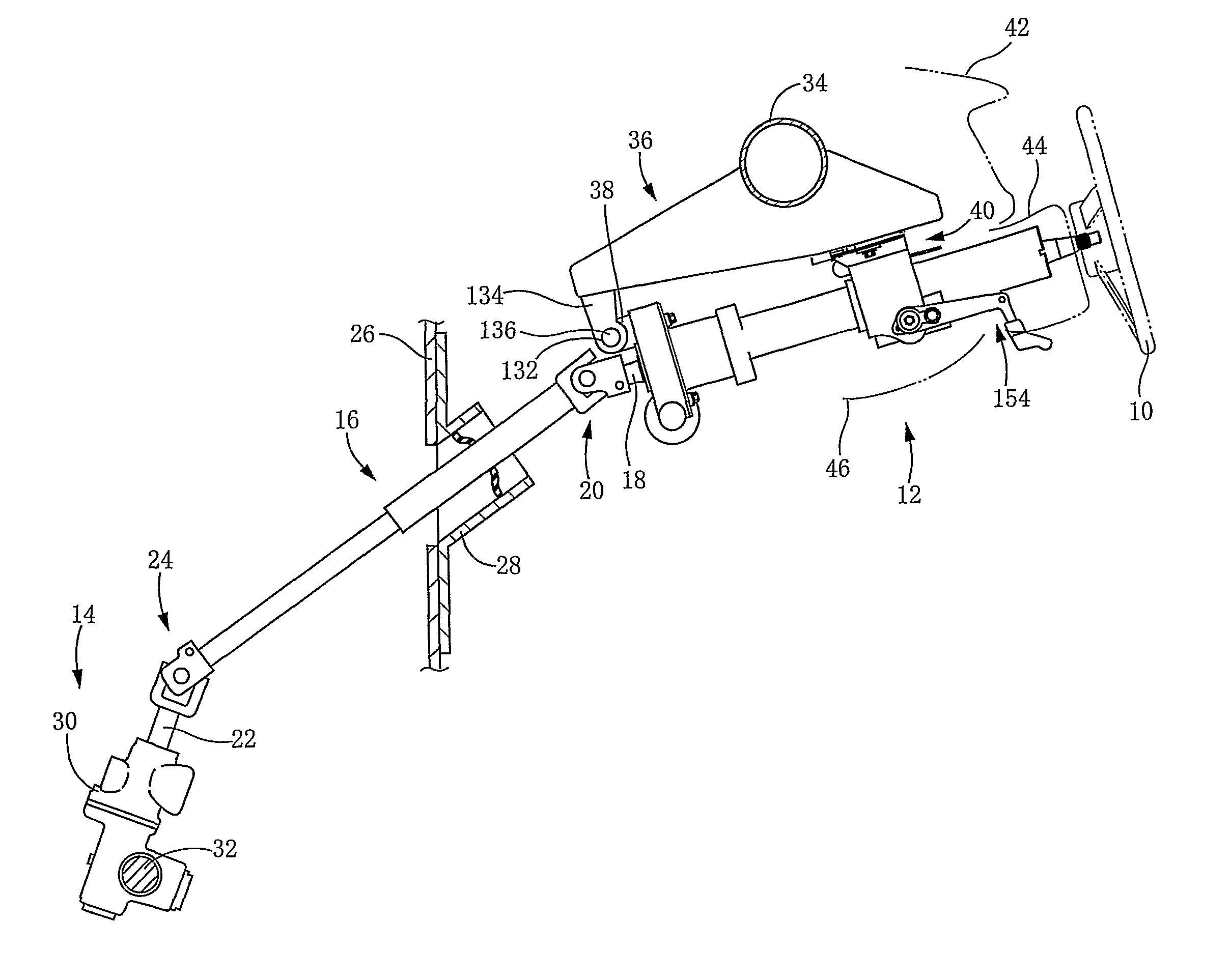
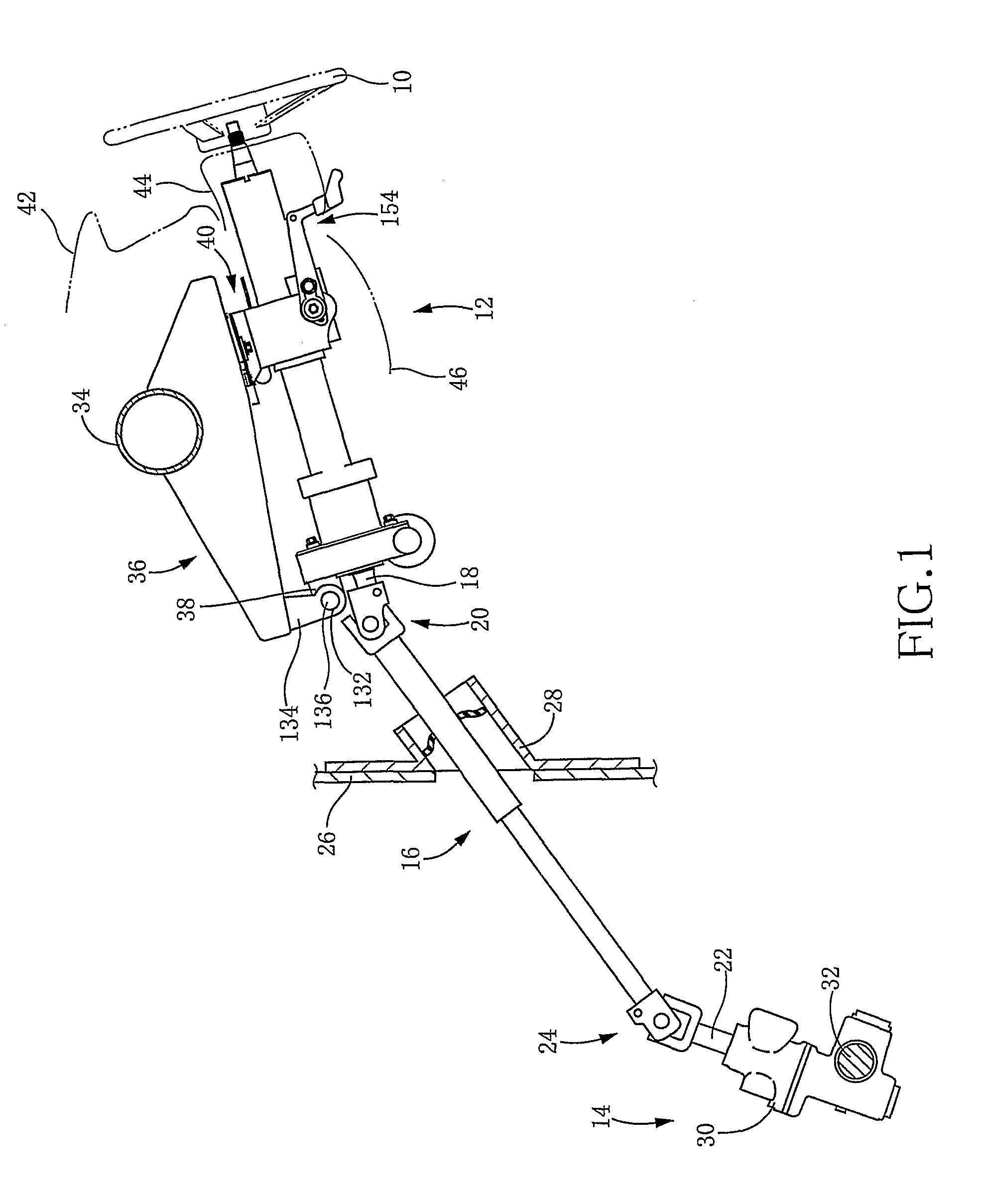
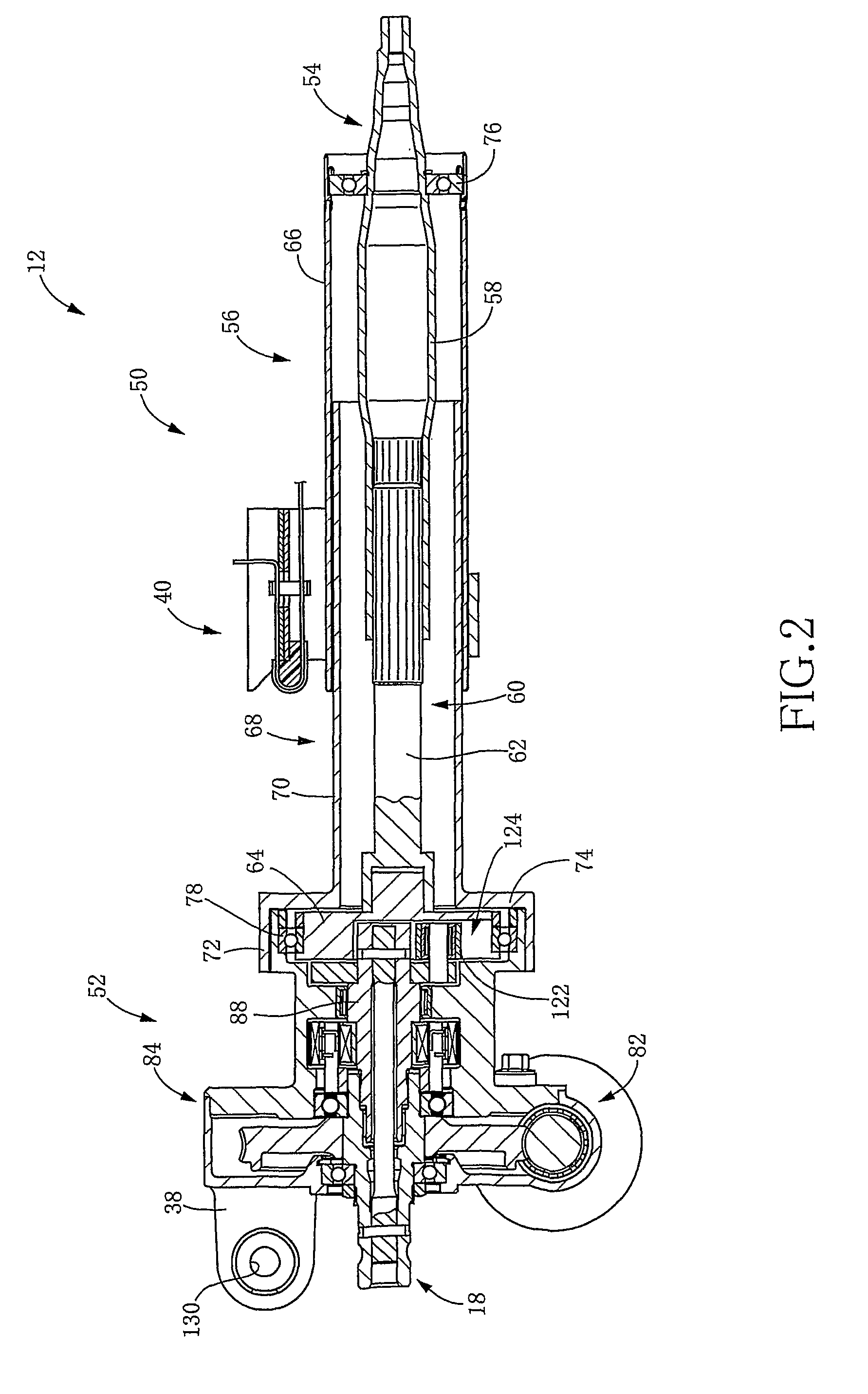
[0076]FIG. 1 shows an overall construction of a vehicle steering system that is to be installed on a vehicle. The vehicle steering system is provided with a steering-force transmitting apparatus that is constructed according to a first embodiment of the invention. The present steering system includes: a steering wheel 10 as a steering operation member operable by an operator of the vehicle; a steering-force transmitting apparatus 12; a wheel turning device 14 configured to turn wheels of the vehicle; and an intermediate shaft 16 that is disposed between the steering-force transmitting apparatus 12 and the wheel turning device 14. The steering wheel 10 is held by an axial end portion of the steering-force transmitting apparatus 12. A universal joint 20 is provided to interconnect an axial end portion of the intermediate shaft 16 and an output shaft 18 that is included in the steering-force transmitting apparatus 12. Meanwhile, another univers...
second embodiment
[0107]There will be described a steering-force transmitting apparatus 200 that is constructed according to a second embodiment of the invention. The present steering-force transmitting apparatus 200 is provided with an EPS section 202 which is different in construction from the EPS section 52 provided in the above-described apparatus 12 constructed according to the first embodiment. The EPS section 202 has an EPS housing 204 in which the output shaft 18 is rotatably supported at their portions that are different from those in the above-described EPS housing 84 of the EPS section 52. Except for this different part of the EPS section, the steering-force transmitting apparatus 200 is substantially the same as the above-described apparatus 12. In the following description as to the apparatus 200 of this second embodiment, the same reference signs as used in the above-described apparatus 12 will be used to identify the functionally corresponding elements, and redundant description of the...
third embodiment
[0111]It is preferable that the torsion bar included in the output shaft is as long as possible in view of its required stiffness. However, where the required stiffness can be obtained even with reduction of the axial length of the torsion bar, the axial length of the output shaft can be reduced by the reduction of the axial length of the torsion bar. Further, the entire axial length of the steering-force transmitting apparatus can be reduced by the reduction of the axial length of the output shaft. It is preferable to reduce the entire axial length of the steering-force transmitting apparatus in view of a limited space available for installation of the apparatus onto the vehicle. In the steering-force transmitting apparatus 12 of the first embodiment shown in view (a) of FIG. 12, the bearings 100, 102, rotational angle sensor 108 and worm wheel 106 are arranged with little clearance therebetween in a portion of the outer circumferential surface of the output shaft 18, which portion...
PUM
 Abstract
Description
Claims
Application Information
 - R&D
- Intellectual Property
- Life Sciences
- Materials
- Tech Scout
- Unparalleled Data Quality
- Higher Quality Content
- 60% Fewer Hallucinations
Browse by: Latest US Patents, China's latest patents, Technical Efficacy Thesaurus, Application Domain, Technology Topic, Popular Technical Reports.
© 2025 PatSnap. All rights reserved.Legal|Privacy policy|Modern Slavery Act Transparency Statement|Sitemap|About US| Contact US: help@patsnap.com


