Method and system for improving diastolic function of the heart

a diastolic function and diastolic technology, applied in the field of diastolic function improvement methods and systems, can solve the problems of pulmonary congestion and peripheral edema, and achieve the effects of preventing the restriction of the myocardium, enabling versatility and modularity of the implantation procedure, and increasing the variability of the total for

Active Publication Date: 2013-02-26
CORASSIST CARDIOVASCULAR LTD
View PDF18 Cites 38 Cited by
  • Summary
  • Abstract
  • Description
  • Claims
  • Application Information

AI Technical Summary

Benefits of technology

[0019]In one specific embodiment of the invention the elastic elements comprise torsion springs and two arms forming a “V”-like shape, wherein each of the arms comprises a curved fastener. The curved fasteners may be shaped in a form of a spiral, or a “G”-like shape, capable of being engaged in anchoring loops provided in the attachment elements. The end portion of each arm may be curved into an “S”-like shape, wherein the bottom part of the “S”-like shape is further curved to provide the spiral, or a “G”-like shape curved fastener. This configuration may be advantageously employed for engaging the curved fasteners of adjacent elastic elements at opposing sides of an anchoring loop of an attachment element, such that opposing tangential mechanical forces applied by the adjacent elastic elements over the attachment element are substantially canceled. This configuration advantageously minimizes the wear between the attachment elements and the elastic elements, substantially facilitates the implantation procedure (by attaching the elastic element to the attachment element), and efficiently prevents unintended release of the elastic elements from the attachment elements.
[0020]Advantageously, each elastic element is comprised of a relatively straight arm and an arm having a curved section relative to the plane of the torsion spring and the relatively straight arm of the elastic element, thereby permitting the crossing of an arm having a curved section of a first elastic element with a relatively straight arm of an adjacent elastic element, while preventing physical contact therebetween.
[0023]The attachment elements may be formed in a shape of a helix having an attachment section and a head section, wherein the attachment section is adapted to be threaded into a tissue and the head section comprises the anchoring means. The attachment element may further comprise a neck section, provided between the attachment section and the head section, said neck section is adapted to prevent excess threading of the attachment element into the tissue. Preferably, the neck section is formed by abruptly reducing the distances between the helix loops above the attachment section of the attachment element.
[0025]Alternatively, the attachment elements are a type of intramural anchor having one or more barbs attached to a nail section of the intramural anchor and configured to be introduced into the tissue and prevent departure of the attachment element after it is inserted into the tissue. More particularly, the barbs are pressed along portions of the nail section of the intramural anchor during insertion into the tissue, and thereafter their state is changed into an “open” state by slightly pulling the intramural anchor proximally such that the proximal sides of the barbs are moved radially away from the nail section, while the distal side of the barbs remain attached thereto. This attachment element preferably comprises anchoring means such as the anchoring loop which plane is substantially parallel to, or coincides with, a concentric axis of the attachment element. The attachment element may further comprise stoppers provided near the anchoring means and adapted to prevent excessive insertion thereof into the tissue, and to further prevent departure of the attachment element therefrom.
[0027]The device of the present invention is different from the devices described in WO 2004 / 066805 by virtue of the curved fasteners formed at the extremities of the device. This feature is highly advantageous in that it permits the practitioner to connect a series of such devices in the form of chains or rows along the heart wall. In particular, the use of substantially parallel rows of the elements has been found to be particularly advantageous for: preventing restriction of the myocardium, enabling versatility and modularity of the implantation procedure, as well as in increasing the variability of the total force supplied to the myocardium (e.g. a structure of strong medial elastic elements and relatively weaker peripheral elastic elements).

Problems solved by technology

The cardinal manifestations of HF are dyspnea and fatigue, which may limit exercise tolerance, and fluid retention, which may lead to pulmonary congestion and peripheral edema.

Method used


Image

  • Method and system for improving diastolic function of the heart
  • Method and system for improving diastolic function of the heart
  • Method and system for improving diastolic function of the heart

Examples


Embodiment Construction

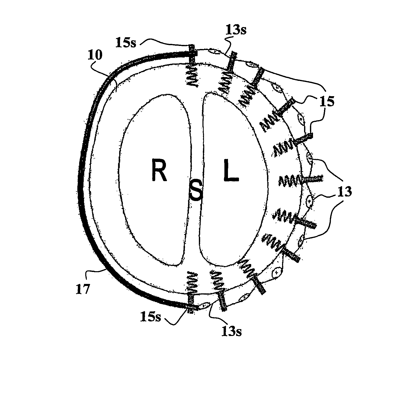
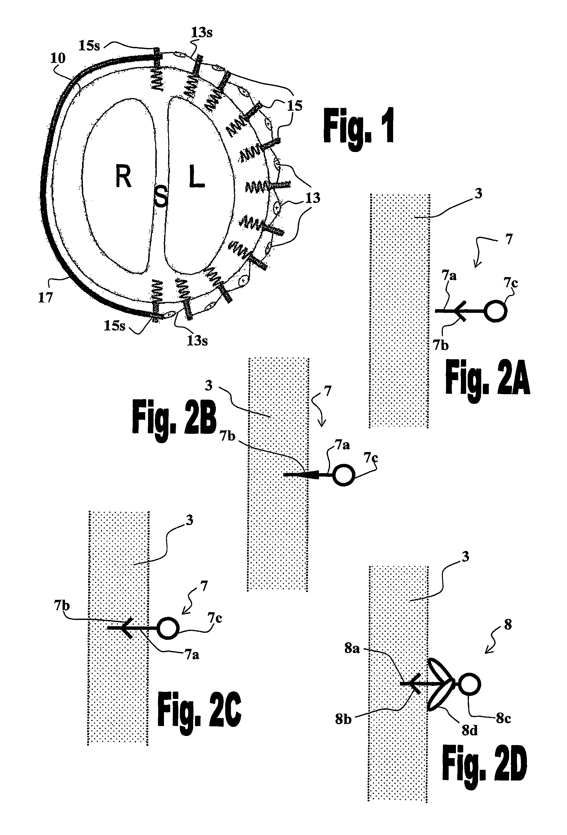
[0066]The present invention provides various embodiments of ventricular function assisting devices designed for treating diastolic and / or systolic dysfunctions. The devices of the invention are designed to assist in the operation of the heart by aiding in reducing the pressures thereinside during systolic function, and aiding in increasing the pressure during diastolic function. The present invention further provides means for mounting a ventricular function assisting device of the invention on the wall of the heart of a treated subject.

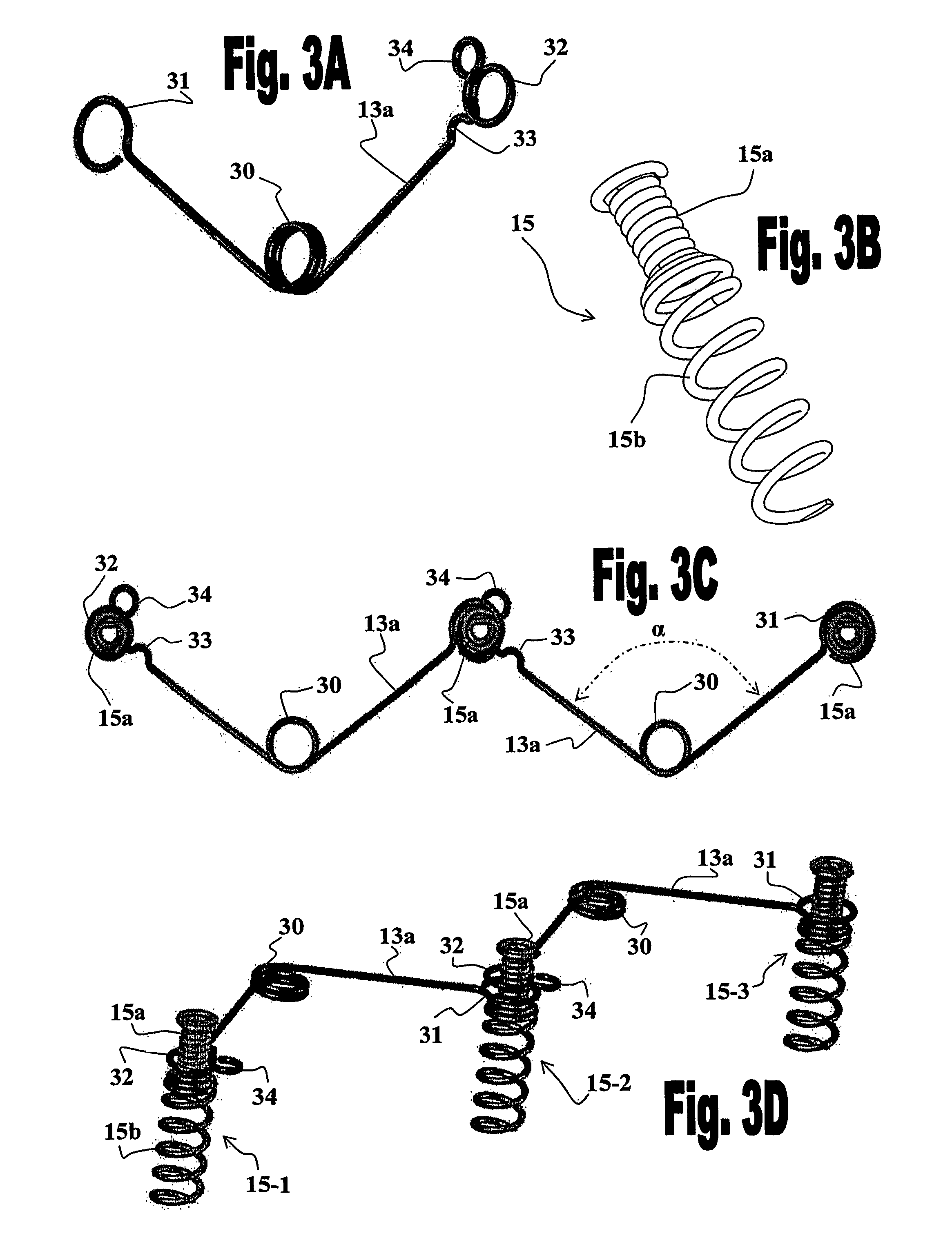
[0067]FIG. 1 illustrates a preferred embodiment of the invention wherein a sequence of elastic elements 13 are mounted over the outer wall of the left ventricle (L), and an elastic wire or stretchable cord 17 is mounted over the outer wall of the right ventricle (R), of heart 10, by means of attachment elements 15. Elastic elements 13 preferably have a “U” or “V” like shape which arms include detachable means at their ends for detachably connecting t...


PUM


Abstract

The present invention provides a system for improving diastolic function of the heart comprising elastic elements and attachment elements, wherein said elastic elements and said attachment elements are configured such that they are capable of being interconnected to form a chain formed of an alternating series of said elastic elements and said attachment elements, and wherein said attachment elements are adapted to be anchored in the wall of the heart and with option for drug delivery to the wall of the heart. The invention further provides devices, methods and kits, for mounting the ventricular function assisting device of the invention.

Description

[0001]This application is the U.S. national phase of International Application No. PCT / IL2007 / 001180, filed 25 Sep. 2007, which designated the U.S. and claims the benefit of U.S. Provisional Application No. 60 / 846,748, filed 25 Sep. 2006, the entire contents of each of which are hereby incorporated by reference.FIELD OF THE INVENTION[0002]The present invention relates to methods and devices for improving ventricular function of the heart and, more particularly, to in-vivo methods and devices for improving diastolic function of the left ventricle of the heart.BACKGROUND OF THE INVENTION[0003]Heart failure (HF) is a complex clinical syndrome that can result from any structural or functional cardiac disorder that impairs the ability of the ventricle to fill with or eject blood. The cardinal manifestations of HF are dyspnea and fatigue, which may limit exercise tolerance, and fluid retention, which may lead to pulmonary congestion and peripheral edema. Heart failure is most commonly ass...

Claims


Application Information

Patent Timeline
Patent Type & Authority Patents(United States)
IPC IPC(8): A61F2/00A61F13/00
CPCA61B17/00234A61B17/0644A61F2/2481A61B17/0401A61B17/068A61F2250/0067A61B2017/0647A61B2017/0649A61F2002/2484A61B2017/00243
Inventor DUBI, SHAYKOVALSKY, IGORFELD, YAIRLOSHAKOVE, AMIRNISHRI, BOAZTUBISHEVITZ, AMIT
Owner CORASSIST CARDIOVASCULAR LTD
Why Eureka
Try Eureka