Rebar cage stiffener ring

a technology of rebar cage and stiffener, which is applied in the field of engineered internal supports for supporting rebar cages, can solve the problems of insufficient structural capacity, significant time and money loss, and insufficient fabricated or inadequate supported cages, so as to ensure the precise placement of the required structural elements, accelerate the fabrication of the cage, and enhance the structural stability

Active Publication Date: 2013-03-05
DIMENSION FABTORS
View PDF33 Cites 10 Cited by
  • Summary
  • Abstract
  • Description
  • Claims
  • Application Information

AI Technical Summary

Benefits of technology

[0005]Disclosed is a substantially annular spacer member, referred to herein as a “stiffener ring” for use in a rebar cage. The stiffener ring enhances structural stability, accelerates fabrication of the cage and guarantees precise placement of the required structural elements.

Problems solved by technology

One of the challenges in manufacturing rebar cages is to ensure structural and dimensional stability is maintained while the cage is being transported, tripped, and set in place.
A poorly fabricated or inadequately supported cage can become unstable under its own weight and collapse on itself, resulting in significant losses in time and money.
Further, inaccurate or uncertain placement of components can result in structural capacity less than that required by codes or designers.

Method used


Image

  • Rebar cage stiffener ring
  • Rebar cage stiffener ring
  • Rebar cage stiffener ring

Examples


Embodiment Construction

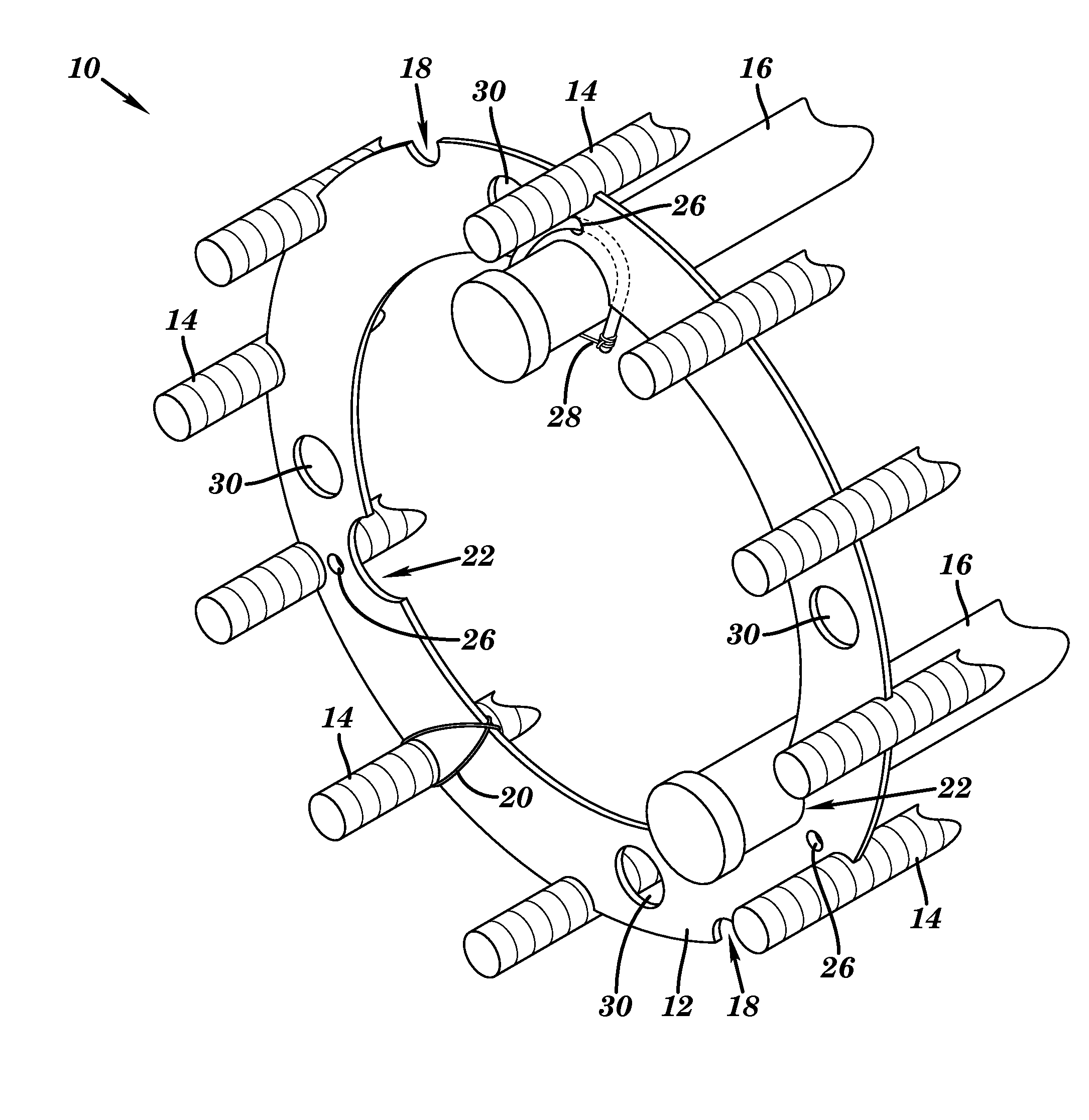
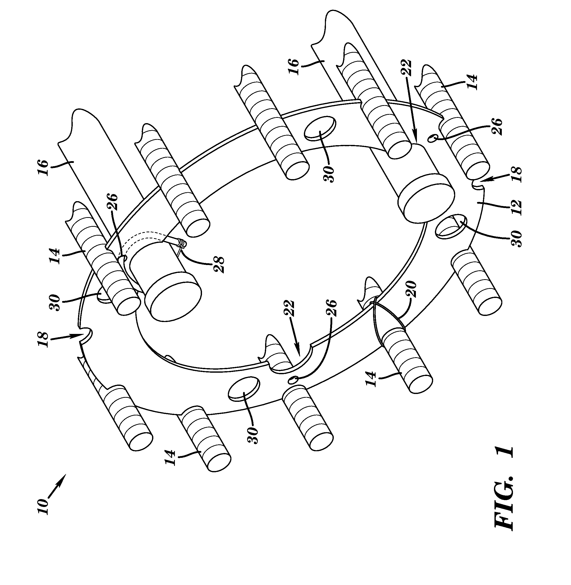
[0020]FIG. 1 depicts an isometric view of an end portion of a rebar cage 10 suitable for use in constructing steel reinforced concrete columns and the like. As shown, rebar cage 10 includes a stiffener ring 12, which has a generally annular shape, and a plurality of transversely mounted steel bars 14 that are seated in a set of primary cutouts 18 about an external (i.e., “outer”) edge of stiffener ring 12. In this embodiment, cutouts 18 comprise generally U-shaped openings that allow a portion of each steel bar's cross-sectional area to sit inside and a portion to sit outside the external edge of the stiffener ring 12. For example, in one illustrative embodiment, approximately half of the circular cross section of the rebar sits in the U-shaped cut-out, and the other half sits outside the opening. Each bar is held in place with a fastening device, e.g., a wire 20 that is manually wrapped around the stiffener ring 12 and bar 14. Alternatively, a bolt, clamp or other fastening device ...


PUM

PropertyMeasurementUnit
diameteraaaaaaaaaa
diameteraaaaaaaaaa
cross-sectional areaaaaaaaaaaa

Abstract

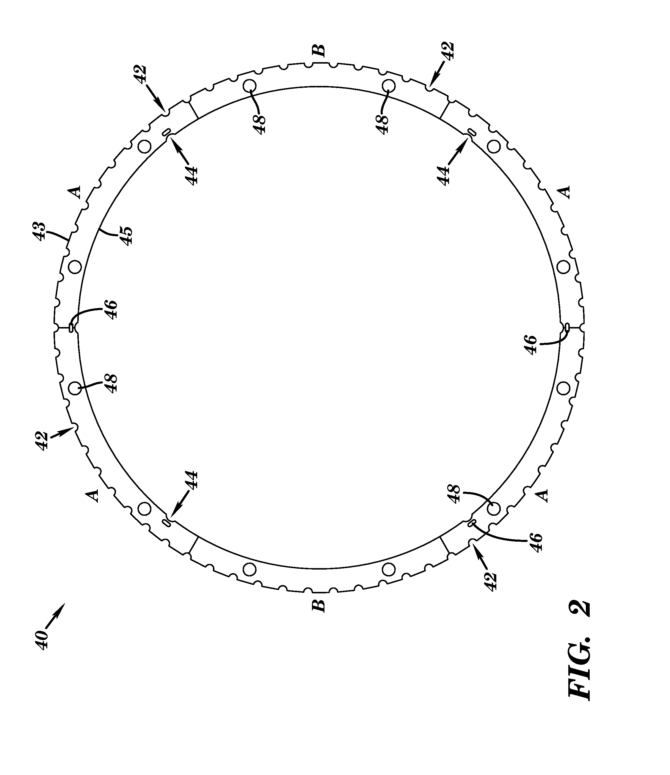
A stiffener ring, and associated method and program product. A stiffener ring is provided having a generally annular shape for supporting a rebar cage, including: a plurality of primary cutouts spaced about an exterior edge of the stiffener ring, wherein each primary cutout is configured to receive a transversely mounted steel bar; a plurality of secondary cutouts spaced about an edge of the stiffener ring, wherein each of the secondary cutouts is configured to received an instrumentation pipe; and a set of flow holes cut into the stiffener ring to facilitate a flow of concrete through the stiffener ring.

Description

BACKGROUND[0001]The present invention relates to rebar cage assemblies for use in reinforced concrete structures, and more particularly relates to a system of engineered internal supports for supporting a rebar cage.[0002]Concrete structures, such as columns and the like, are typically constructed with a steel bar (rebar) cage. The rebar cage is generally cylindrical in shape with circular spacer members that support transversely running steel bars. The particular specifications and dimensions of a given rebar cage can depend on any number of factors, including, e.g., the size of the concrete structure being built, the engineering requirements, soil conditions, wind loads, etc. Based on developments in excavating and drilling equipment, it is no longer unusual for a cage to be 60 or more feet long, ten or so feet in diameter, and weigh tens of thousands of pounds. U.S. Pat. No. 4,467,583 issued to Hasak on Aug. 28, 1984, which is hereby incorporated by reference, describes such a st...

Claims


Application Information

Patent Timeline
Patent Type & Authority Patents(United States)
IPC IPC(8): E04C5/065
CPCE04C5/0604E04C5/163Y10T29/49963Y10T29/49954Y10T29/49959
Inventor STEVENS, SCOTT D.STEVENS, GREG B.
Owner DIMENSION FABTORS
Why Eureka
Try Eureka