
Method and apparatus for a downhole gas generator

a gas generator and downhole technology, applied in the direction of water supply installation, wellbore/well accessories, insulation, etc., can solve the problems of significant environmental problems, difficult and expensive hydrocarbon recovery, and unstable wellbore, so as to avoid overheating and minimize the formation of deposits

Inactive Publication Date: 2013-03-05
WORLD ENERGY SYST
View PDF80 Cites 17 Cited by
  • Summary
  • Abstract
  • Description
  • Claims
  • Application Information

AI Technical Summary

Benefits of technology

The apparatus efficiently generates superheated steam at depth, reducing hydrocarbon viscosity and improving oil recovery while minimizing material failures and environmental impacts by controlling heat transfer and maintaining stable combustion.

Problems solved by technology

The high viscosity makes it difficult and expensive to recover the hydrocarbon.
Steam cannot be injected though the permafrost layer because the heat could potentially expand the permafrost, causing wellbore stability issues and significant environmental problems with melting permafrost.
Additionally, the current methods of producing heavy oil reservoirs face other limitations.
One such problem is wellbore heat loss of the steam, as the steams travels from the surface to the reservoir.
This problem is worsened as the depth of the reservoir increases.
This situation lowers the energy efficiency of the oil recovery process.
DHSGs, however, also present numerous challenges, including excessive temperatures, corrosion issues, and combustion instabilities.
These challenges often result in material failures and thermal instabilities and inefficiencies.

Method used


Image

  • Method and apparatus for a downhole gas generator
  • Method and apparatus for a downhole gas generator
  • Method and apparatus for a downhole gas generator

Examples


Embodiment Construction

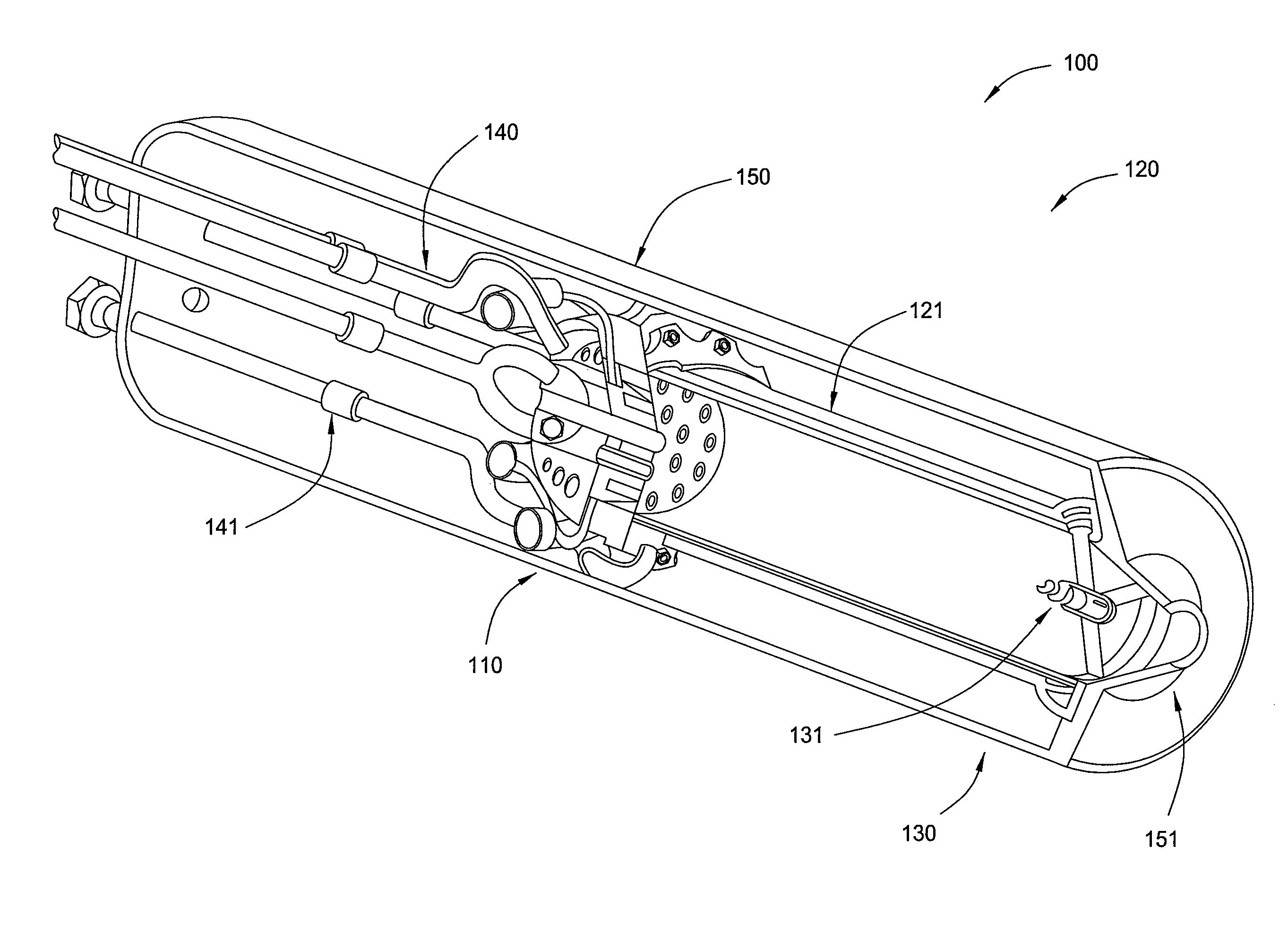
[0041]Embodiments of the invention generally relate to an apparatus and method of use of a downhole steam generator (DHSG). As set forth herein, embodiments of the invention will be described as they relate to a DHSG and heavy oil reservoirs. It is to be noted, however, that aspects of the invention are not limited to use with a DHSG, but are applicable to other types of systems, such as other downhole mixing devices. It is to be further noted, however, that aspects of the invention are not limited to use in the recovery of heavy oil, but are applicable to use in the recovery of other types of products, such as gas hydrates. To better understand the novelty of the apparatus of the invention and the methods of use thereof, reference is hereafter made to the accompanying drawings.

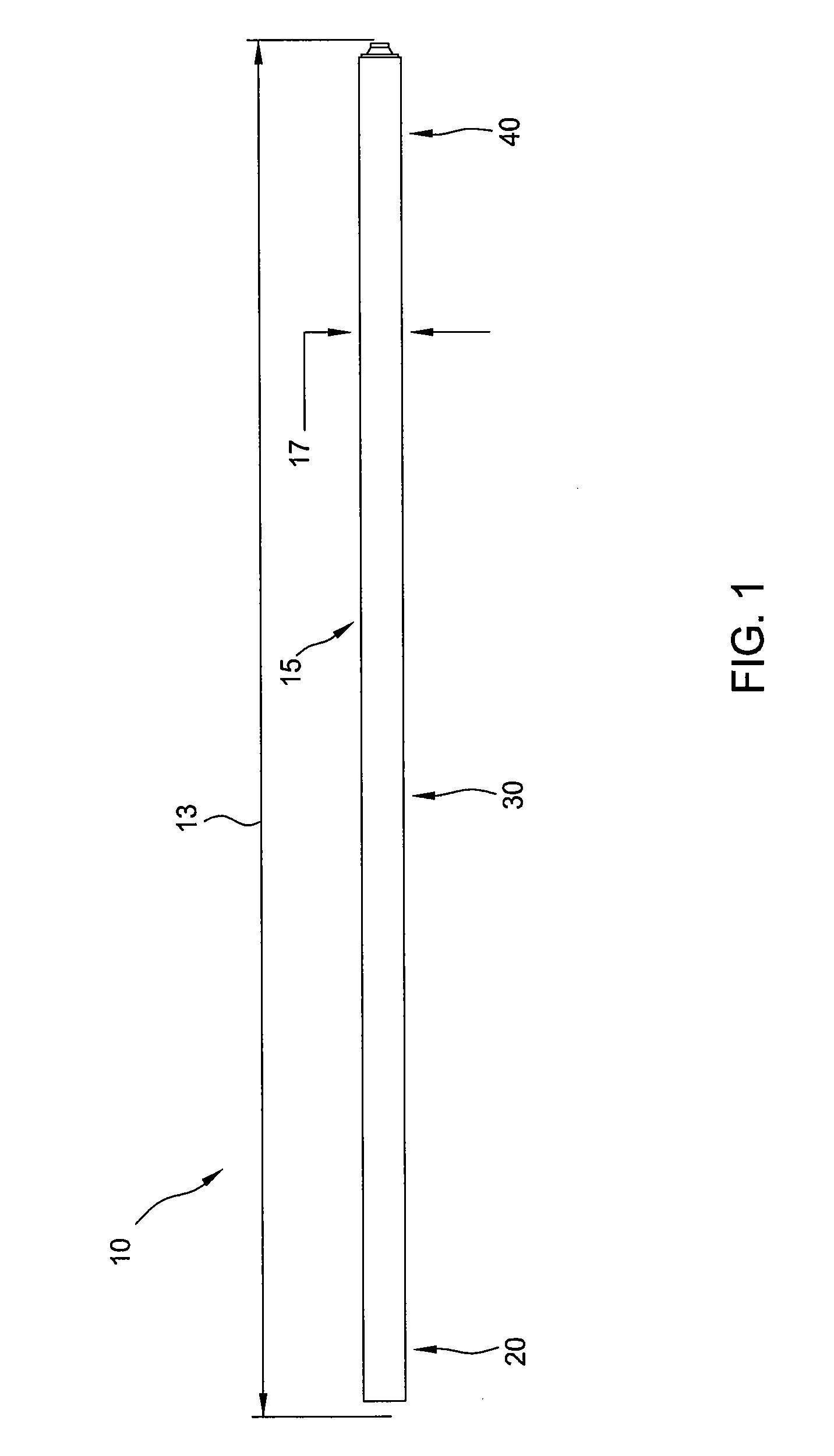
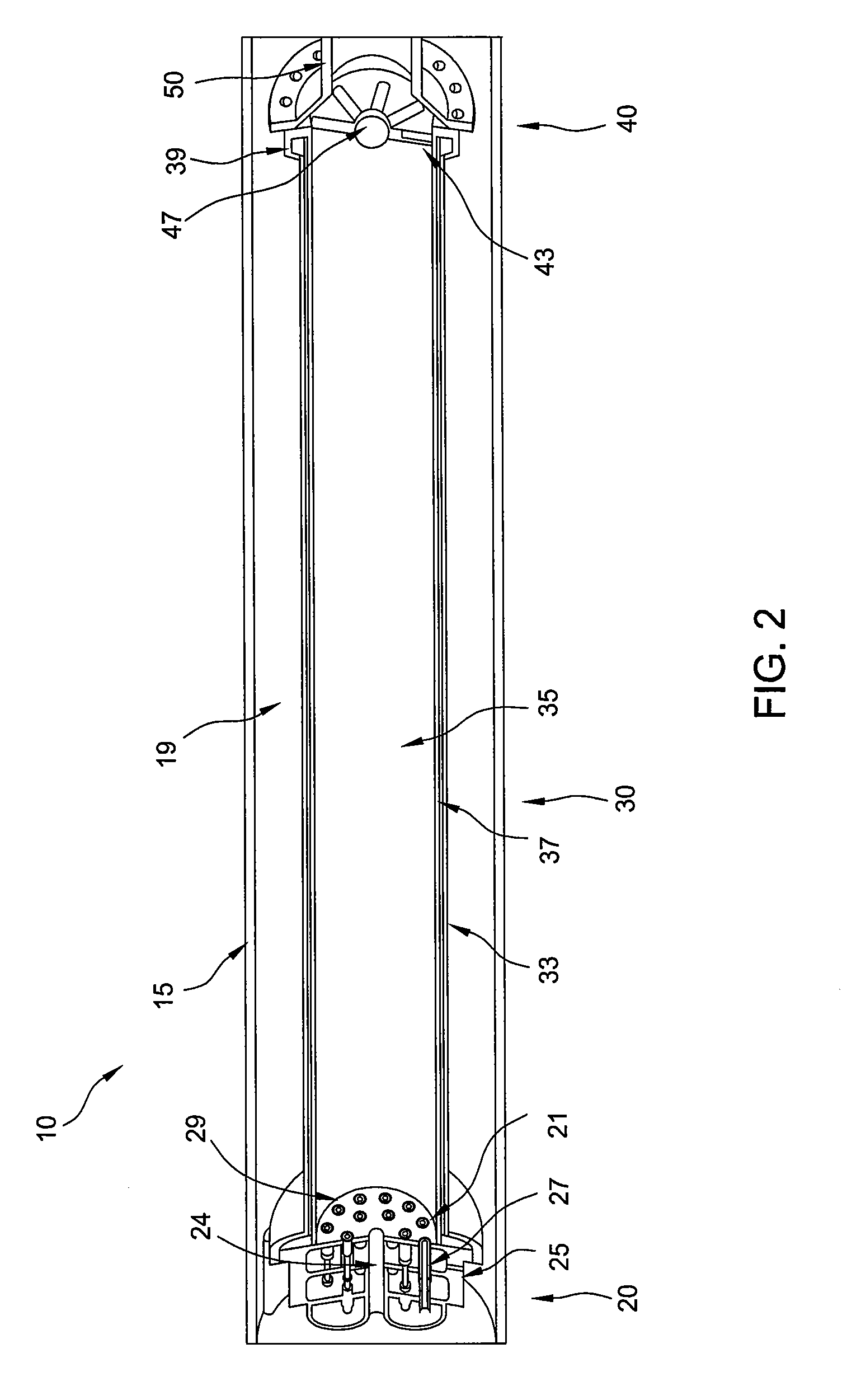
[0042]FIG. 1 illustrates a DHSG 10 according to one embodiment. The DHSG 10 may be utilized with various and multiple wellbore configurations, including vertical, horizontal, or combinations thereof. In addit...


PUM


Abstract

A downhole steam generation apparatus and method of use are provided. The apparatus may include an injection section, a combustion section, and an evaporation section. The injection section may include a housing, injector elements, and injector plate. The combustion section may include a liner having channels disposed therethrough. The evaporation section may include conduits in fluid communication with the channels and the combustion chamber, and a nozzle operable to inject a fluid from the channels to the combustion chamber in droplet form. A method of use may include supplying fuel, oxidant, and fluid to the apparatus; combusting fuel and oxidant in a chamber while flowing the fluid through a plurality of channels disposed through a liner, thereby heating the fluid and cooling the liner; and injecting droplets of the heated fluid into the chamber and evaporating the droplets by combustion of the fuel and the oxidant to produce steam.

Description

CROSS REFERENCE TO RELATED APPLICATIONS[0001]This application claims benefit of U.S. Application Ser. No. 61 / 226,642, filed Jul. 17, 2009, and U.S. Application Ser. No. 61 / 226,650, filed Jul. 17, 2009, which are herein incorporated by reference in their entirety.BACKGROUND OF THE INVENTION[0002]1. Field of the Invention[0003]Embodiments of the invention relate to downhole steam generators.[0004]2. Description of the Related Art[0005]There are extensive viscous hydrocarbon reservoirs throughout the world. These reservoirs contain a very viscous hydrocarbon, often called “bitumen,”“tar,”“heavy oil,” or “ultra heavy oil,” (collectively referred to herein as “heavy oil”) which typically has viscosities in the range from 3,000 to over 1,000,000 centipoise. The high viscosity makes it difficult and expensive to recover the hydrocarbon.[0006]Each oil reservoir is unique and responds differently to the variety of methods employed to recover the hydrocarbons therein. Generally, heating the h...

Claims


Application Information

Patent Timeline
Patent Type & Authority Patents(United States)
IPC IPC(8): E21B43/24
CPCE21B43/24E21B36/02Y10T137/0318Y10T137/8593
Inventor TILMONT, DANIELALIFANO, JOSEPH ANTHONYJOS, CYRIL CHERIANWARE, CHARLES H.FOLSOM, BLAIR A.
Owner WORLD ENERGY SYST
Learn More