
Hyperextension knee brace

a knee brace and hyperextension technology, applied in the field of knee orthosis devices, can solve the problems of increased lateral trunk displacement, normal gait, and increased energy consumption while walking, and achieve the effect of optimizing knee support and control, reducing patient exertion, and improving comfor

Active Publication Date: 2013-03-05
NACE RICHARD NACE
View PDF6 Cites 4 Cited by
  • Summary
  • Abstract
  • Description
  • Claims
  • Application Information

AI Technical Summary

Benefits of technology

[0009]First, the patient can inflate or deflate the air bladder to provide optimal support and control of knee movement depending on patient activity without having to make adjustments to the hyperextension bar which usually requires the use of tools and potentially the assistance of a professional fitter, known as an orthotist, or another skilled practioner.
[0010]Secondly, comfort is significantly improved with the present knee brace because a considerable amount of force placed onto the back of the knee with each step is absorbed by the air bladders and forces a reactive “push back,” which reduces patient exertion.
[0011]Thirdly, the reactive “push back” provided by the air bladder facilitates normal gait biomechanics thereby improving patient gait with less expenditure of energy, greater step and stride length and a reduction in postural trunk adjustments to “unload” the knee for lessening the hyperextension moment of the knee joint.
[0012]Further, the use of an adjustable inflatable air bladder positioned between the hyperextension stop component of the knee brace and the patient's leg creates a dynamic brace as opposed to a static one. The inflated air bladder will absorb the hyperextension moment of the knee joint and push back behind the knee as the air bladder returns to its inflated shape. This absorption significantly improves comfort for the patient because the posterior movement of the knee joint is absorbed as the air bladder is compressed. The reactive “push back” of the air bladder to its inflated shape also provides a dynamic forward movement of the knee joint to facilitate a more normal knee movement by converting the posterior movement into an anterior movement force. Instead of a static block, the brace becomes a dynamic assist in controlling and reversing hyperextension of the knee, which a static block cannot do. The “halting” gait of a static hyperextension block design, as seen in the prior art, is therefore significantly reduced and the use of inflatable air bladder instead leads to improvements in gait and as well less energy expenditure by the patient to ambulate. As a result, the patient's step length improves. Further, the balance of time spent on each leg during gait improves resulting in a more balanced gait for the person suffering from genu recurvatum.

Problems solved by technology

The posterior deviation of the knee joint (specifically in the tibiofemoral joint) disrupts normal gait and can negatively affect step length, stride length, gait velocity, walking cadence, increased lateral trunk displacement, and increased energy consumption while walking.
If untreated, genu recurvatum can lead to significant knee joint deformities, which negatively affects walking ability and can predispose a patient to serious knee injury, knee pain and even cause knee osteoarthritis.
This disrupts a normal gait pattern, requires significant additional energy to ambulate and can result in significant discomfort behind the knee when ambulating over extended distances.

Method used


Image

  • Hyperextension knee brace
  • Hyperextension knee brace
  • Hyperextension knee brace

Examples


Embodiment Construction

, contained herein below, may be better understood when accompanied by a brief description of the drawings, wherein:

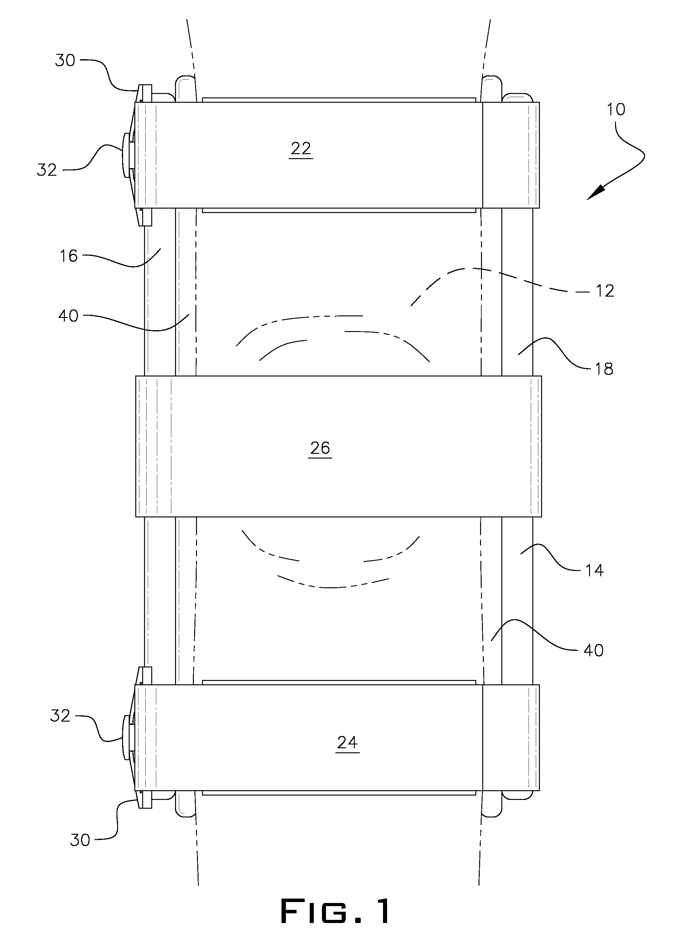
[0015]FIG. 1 is a front elevational view of the novel hyperextension knee brace of the present invention shown to be employed on a knee of a patient suffering from genu recurvatum;

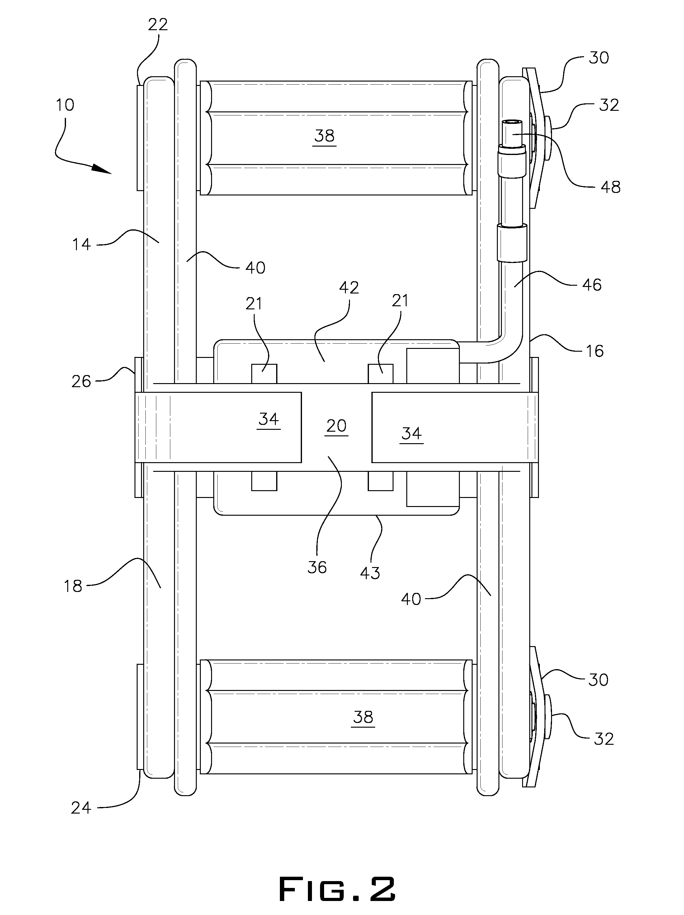
[0016]FIG. 2 is a rear elevational view of the hyperextension knee brace of the present invention;

[0017]FIG. 3 is a left elevational view of the hyperextension knee brace of the present invention;

[0018]FIG. 4 is a right elevational view of the hyperextension knee brace of the present invention;

[0019]FIG. 5 is a top plan view of the hyperextension knee brace of the present invention;

[0020]FIG. 6 is a bottom plan view of the hyperextension knee brace of the present invention;

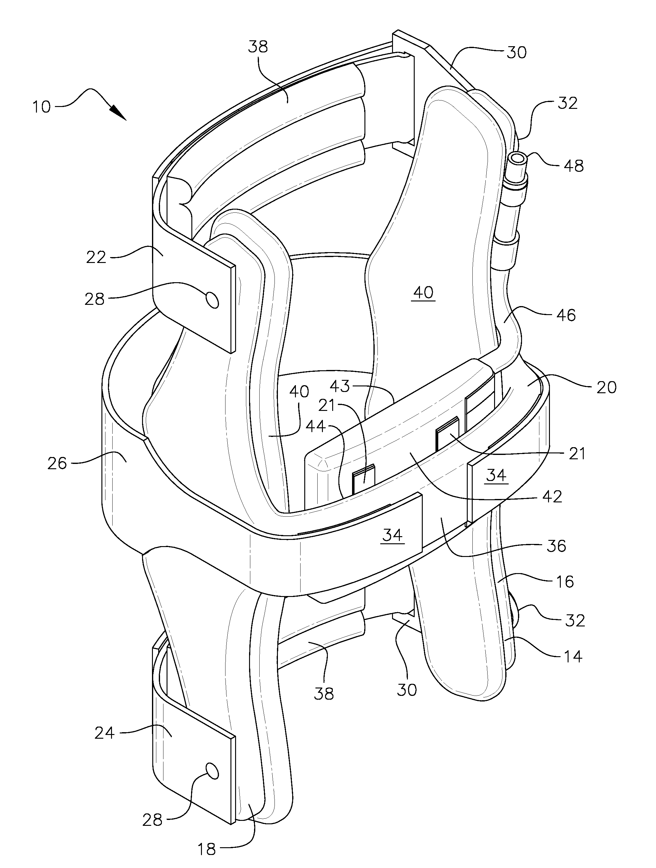
[0021]FIG. 7 is a front perspective view of the hyperextension knee brace of the present invention; and

[0022]FIG. 8 is a rear perspective view of the novel hyperextension knee brace of the present invention.

DETAILED DESCRIP...


PUM


Abstract

A knee brace for treating hyperextension in a patient's knee. The knee brace includes two lateral uprights and a back support positioned horizontally to and generally at a middle portion of the lateral uprights. The lateral uprights and the back support define an integral frame. A plurality of straps includes a thigh, shin and patella strap connected at opposed ends to the frame for securing the brace to the patient. A plurality of cushion pads is disposed along inner surfaces of the lateral uprights and the thigh and shin straps for providing comfort and for mitigating brace migration. An inflatable air bladder is located on an inner surface of the back support for positioning behind the knee. The air bladder has an inflation tube for increasing or decreasing the air volume within the air bladder to affect a range of motion for the patient's knee.

Description

PRIOR APPLICATIONS[0001]This application is a continuation-in-part of provisional patent application No. 61 / 410,974, filed Nov. 8, 2010, still pending.FIELD OF THE INVENTION[0002]The present invention relates to a knee orthosis device used in the correction and treatment of genu recurvatum. More particularly, it refers to a knee brace for correcting hyperextension moment of the knee joint and preventing genu recurvatum displacement of the knee during gait.BACKGROUND OF THE INVENTION[0003]Orthotic devices and appliances commonly referred to as “orthotics,” are known in the prior art and have been utilized for many years by doctors, orthotists, physical therapists and occupational therapists. They are primarily used to protect an injured or surgically repaired ankle or knee joint or a weakened joint caused by neurological disability or physiological deformity.[0004]One such deformity is known as genu recurvatum of the knee. Genu recurvatum is a sustained posteriorly directed hyperexte...

Claims


Application Information

Patent Timeline
Patent Type & Authority Patents(United States)
IPC IPC(8): A61F5/00
CPCA61F5/0106
Inventor NACE, RICHARD A.
Owner NACE RICHARD NACE
Learn More