Heating appliance for cooking
a technology for cooking and heating appliances, applied in the direction of ohmic resistance heating, electric/magnetic/electromagnetic heating, pulse technique, etc., can solve the problems of rotary container types that may occasionally provide obstructions to users, indeed tiresome handling, etc., and achieve the effect of increasing the operability and the design feature of the cooking applian
- Summary
- Abstract
- Description
- Claims
- Application Information
AI Technical Summary
Benefits of technology
Problems solved by technology
Method used
Image
Examples
first embodiment
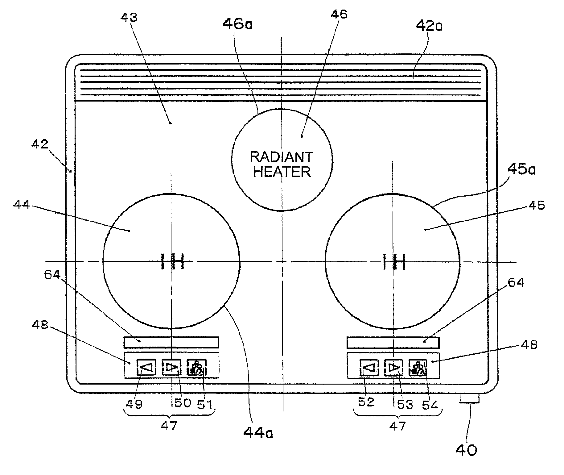
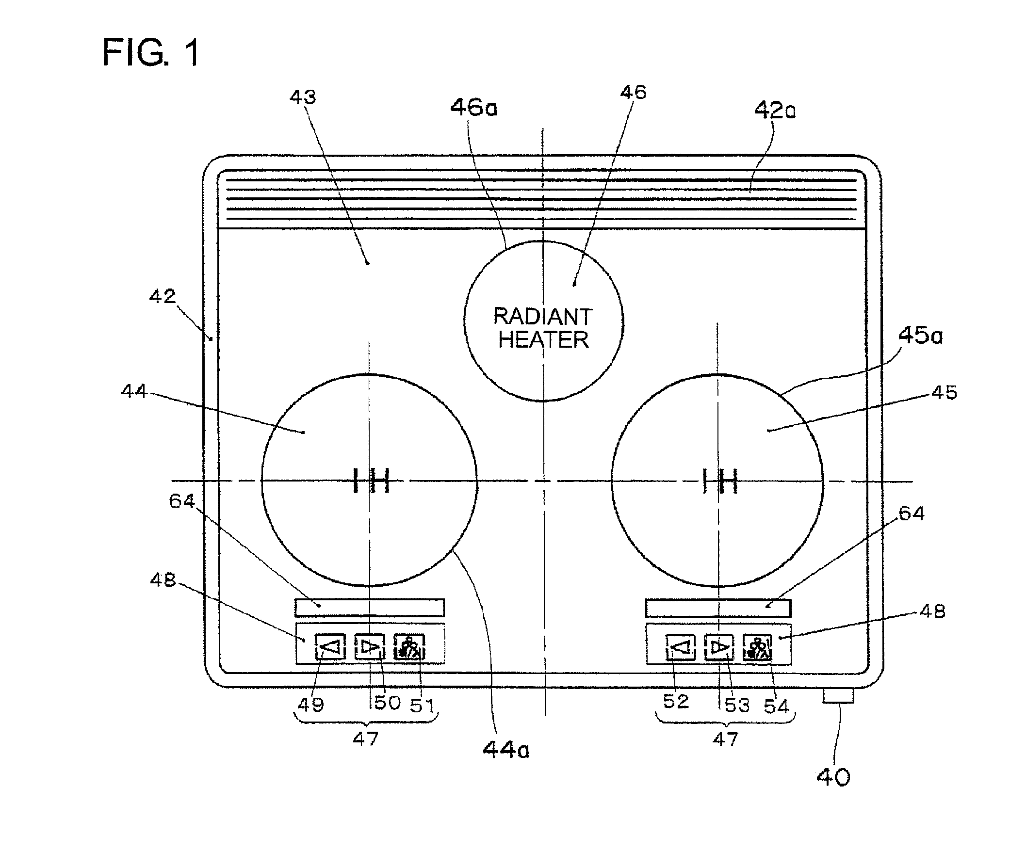
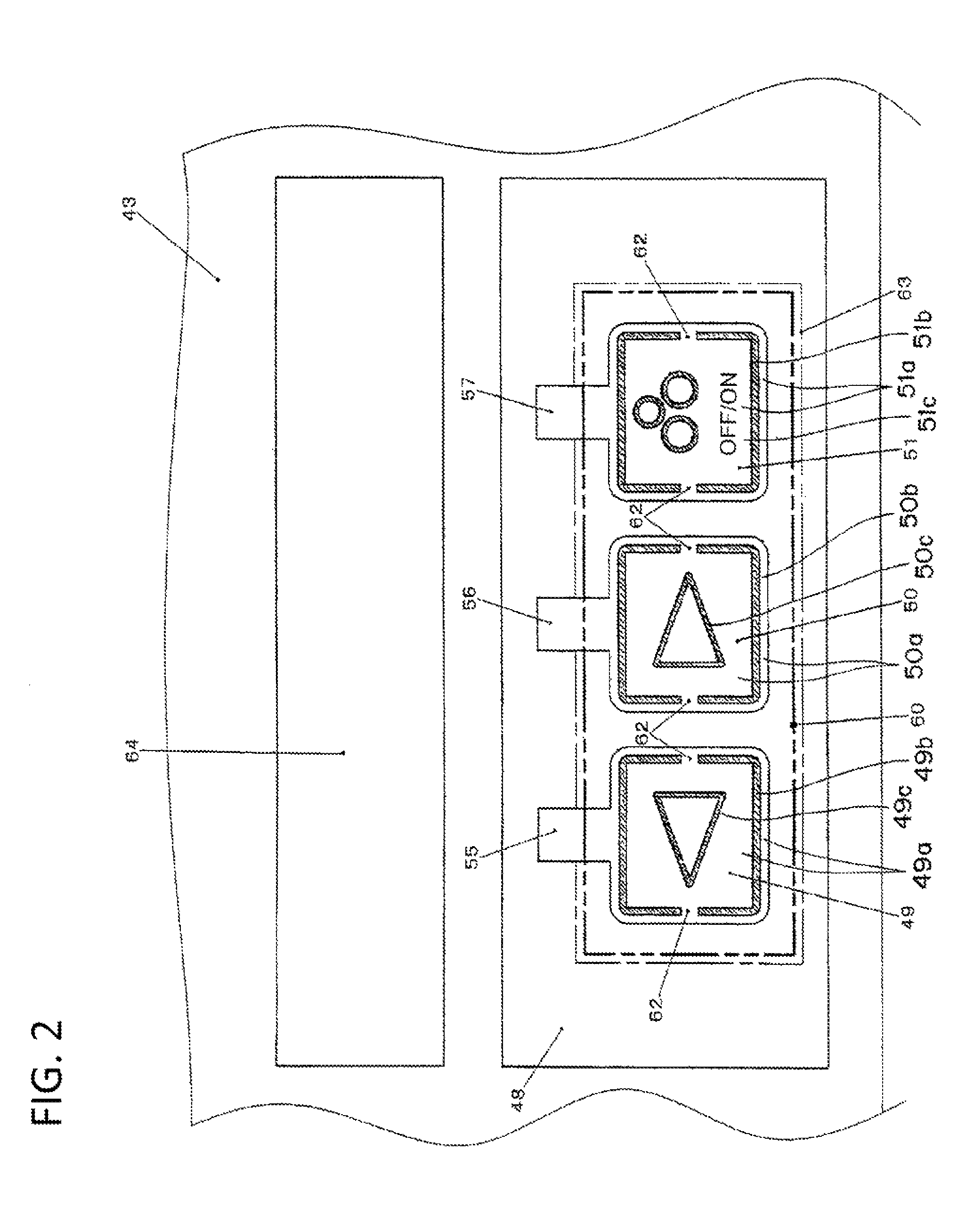
[0034]FIG. 1 is a top plan view showing an induction heating appliance, which is a heating appliance for cooking according to a first preferred embodiment of the present invention, (with operating buttons on a top plate shown as in lighting conditions); FIG. 2 is a fragmentary enlarged top plan view showing the operating buttons (together with detecting units and connectors that are applied to a rear surface of the top plate, but invisible from the front); and FIG. 3 is a fragmentary sectional view showing the operating buttons.
[0035]It is to be noted that parts of the description of the operation of the induction heating appliance itself, which are similar to those described in connection with the prior art cooking appliance with particular reference to FIGS. 9 and 10, are not reiterated for the sake of brevity.
[0036]Referring now to FIGS. 1 to 3, a top plate 43 having an electric insulating property and prepared from a plate member made of a translucent material such as a heat res...
second embodiment
[0050]FIGS. 5 and 6 illustrate a fragmentary perspective view and a fragmentary sectional view showing an important portion of the induction heating appliance, which is the heating appliance for cooking according to a second preferred embodiment of the present invention.
[0051]Referring to FIGS. 5 and 6, a planar light emitting member 71 is formed in a generally L-sectioned configuration. The planar light emitting member 71 has a horizontally laid light emitting body 71b and a light guide portion 71c extending downwardly from one end of the light emitting body 71b, with light sources, for example, light emitting diodes 74 disposed in face-to-face relation with respective end faces 73. In other words, the planar light emitting member 71 is made up of the plate-like light emitting body 71b formed with the light emitting face 71a so as to confront the conductor detecting units 49a to 51a and the plate-like light guide portion 71c lying perpendicular to the light emitting body 71b, and i...
third embodiment
[0054]FIGS. 7 and 8 illustrate a fragmentary perspective view and a fragmentary sectional view showing an important portion of the induction heating appliance, which is the heating appliance for cooking according to a third preferred embodiment of the present invention.
[0055]Planar light emitting members 81 shown in FIG. 7 differ from the planar light emitting member 71 shown in FIG. 5, in that they are separated in correspondence with the operating buttons 49 to 51. Each of the planar light emitting members 81 includes a light emitting portion 81b having a top face defining a light emitting face 81a, a light guide portion 81c, a light incident portion 81d and the end face 81e defining a light incident face of the light incident portion 81d in a manner similar to those shown in FIG. 5. As best shown in FIG. 8, each of the planar light emitting members 81 is encased from below into a holder frame 82 with a side end face of the light emitting portion 81b covered by a side face of the ...
PUM
 Abstract
Description
Claims
Application Information
 - R&D
- Intellectual Property
- Life Sciences
- Materials
- Tech Scout
- Unparalleled Data Quality
- Higher Quality Content
- 60% Fewer Hallucinations
Browse by: Latest US Patents, China's latest patents, Technical Efficacy Thesaurus, Application Domain, Technology Topic, Popular Technical Reports.
© 2025 PatSnap. All rights reserved.Legal|Privacy policy|Modern Slavery Act Transparency Statement|Sitemap|About US| Contact US: help@patsnap.com


