Time domain reflectometry in a coherent interleaved sampling timebase

a time-domain reflectometry and interleaved sampling technology, applied in the field of time-domain reflectometry acquisition samples for a time-domain reflectometry system, can solve the problems of large time jitter and inherently nonlinear delay circuits, and achieve the effect of reducing the dependence of waveform shape and easy minimization

Active Publication Date: 2013-03-05
TELEDYNE LECROY
View PDF11 Cites 2 Cited by
  • Summary
  • Abstract
  • Description
  • Claims
  • Application Information

AI Technical Summary

Benefits of technology

[0007]Therefore, in accordance with the invention, a test and measurement apparatus is provided that relies upon a CIS timebase for sampling in a TDR system. A CIS timebase record length increases as one increases the sampling rate maintaining the time period of the waveform. The sample spacing of a CIS timebase is very linear, since it depends on a sampling clock that is locked to a stable reference clock with a phase lock loop (PLL). PLL jitter, and therefore sampling jitter, is easy to minimize with the designs and components currently available. Generating a TDR voltage step from a stable reference clock ensures the linearity of the sampling with respect to the TDR voltage step. The linear timebase sampling of the TDR voltage step reduces the dependence of the waveform shape on the delay of the TDR voltage step. This allows simple correction of the time position of the TDR voltage step due to temperature and other variations in delay. The delay position of the TDR voltage step and the time window around the TDR voltage step can be adjusted at will without causing any changes in the recording of the reflections due to discontinuities.
[0008]Therefore, in accordance with the invention, a method and apparatus are provided that provide for a more accurate and jitter reducing sampling system for use with a TDR system.

Problems solved by technology

These delay circuits are inherently nonlinear and subject to large time jitter.

Method used


Image

  • Time domain reflectometry in a coherent interleaved sampling timebase
  • Time domain reflectometry in a coherent interleaved sampling timebase
  • Time domain reflectometry in a coherent interleaved sampling timebase

Examples


Embodiment Construction

[0016]A CIS timebase produces a sampling clock locked to a fraction of the input reference clock. Commonly assigned Patent Application US 2006 / 0177018, titled “Coherent Interleaved Sampling” describes such a CIS timebase, the contents of this application being incorporated herein by reference. In accordance with the present invention, a TDR system uses a version of such a CIS timebase. The CIS timebase employed in accordance with this TDR implementation will now be described in greater detail.

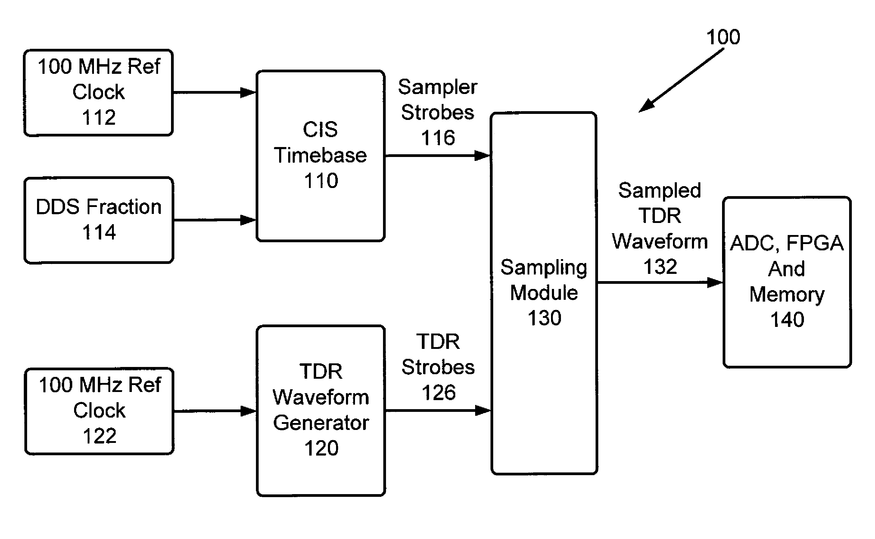
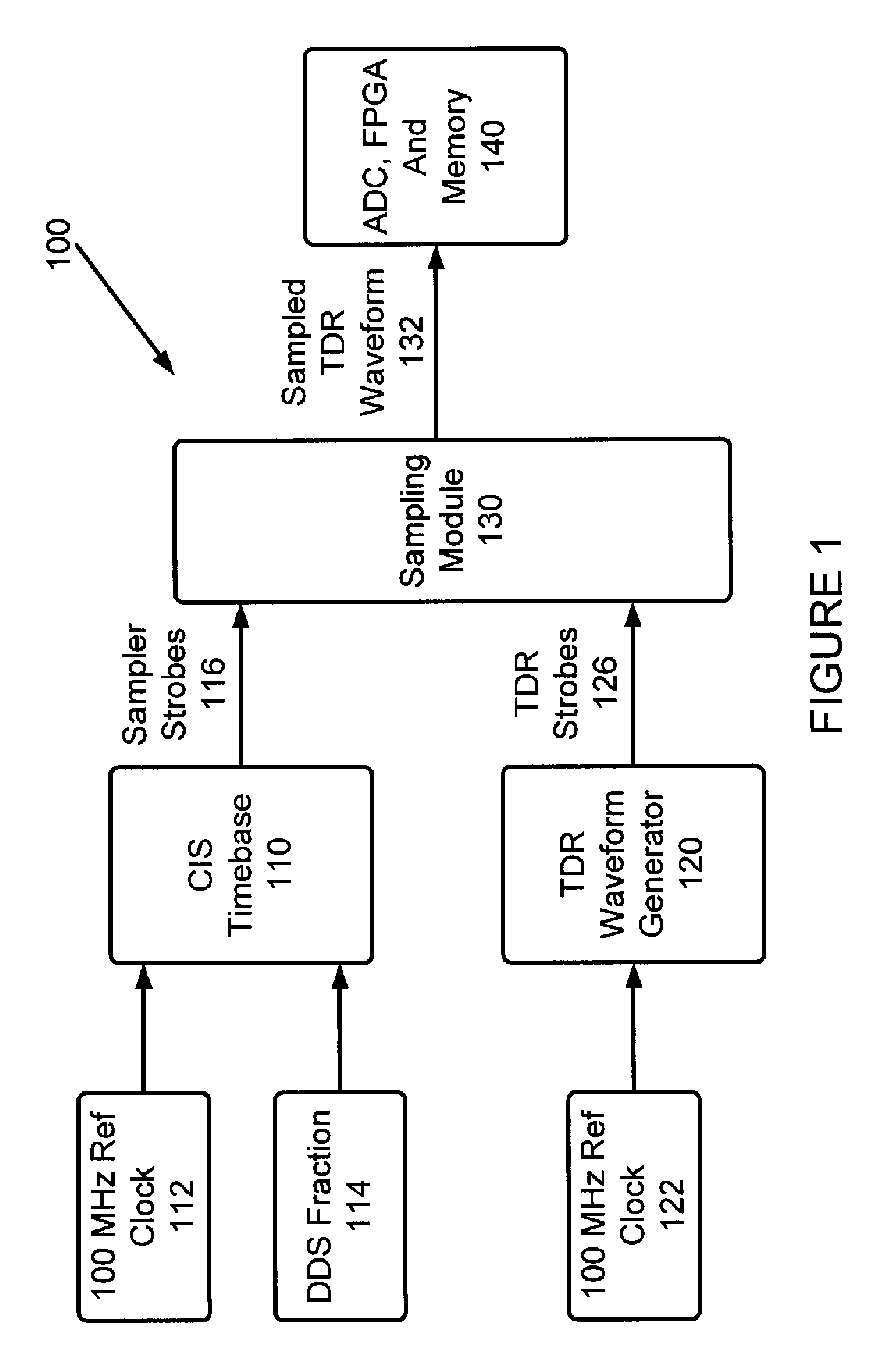
[0017]FIG. 1 is a block diagram depicting a TDR system using a CIS timebase 100 in accordance with an embodiment of the present invention. The TDR system includes a CIS timebase 110 receiving a 100 MHz reference clock 112 and a DDS fraction 114, and a TDR waveform generator 120 receiving a 100 MHz reference clock 122. The CIS timebase is implemented as described in patent application US 2006 / 0177018, and produces sampler strobes 116. The TDR waveform generator produces a voltage step waveform 1...


PUM


Abstract

A system and method for performing a time domain reflectometry measurement. The system includes a coherent interleaved sampling timebase, a sampling strobe generator for generating one or more sampling strobes in accordance with the coherent interleaved sampling timebase, a time domain reflectometry sampling strobe generator for generating one or more time domain reflectometry strobes in accordance with one or more of the generated sampling strobes; and a sampling module for sampling a time domain reflectometry signal in accordance with one or more of the one or more generated sampling strobes and one or more of the one or more generated time domain reflectometry strobes. The system further includes an analog to digital converter for analog to digital converting the samples of the time domain reflectometry signal and a memory for storing the converted samples of the time domain reflectometry signal.

Description

CROSS REFERENCE TO RELATED APPLICATIONS[0001]This application claims the benefit under 35 USC 119 of U.S. Provisional Patent Application Ser. No. 61 / 299,395 filed Jan. 29, 2010, titled “Time Domain Reflectometry in a Coherent Interleaved Sampling Timebase”, currently pending, the contents thereof being incorporated herein by reference.FIELD OF THE INVENTION[0002]This invention is related generally to a method and apparatus for acquiring samples for a time domain reflectometry (TDR) system, and more particularly to the use of a coherent interleaved sampling (CIS) timebase to acquire these samples.BACKGROUND OF THE INVENTION[0003]A TDR system measures the reflections of an incident waveform from impedance discontinuities in the system under test. Typical TDR systems could be sonar to detect underwater objects, ultrasound to detect objects inside the body and as described in this invention, voltage steps to detect discontinuities in electrical systems. A TDR pulse in a TDR system is ty...

Claims


Application Information

Patent Timeline
Patent Type & Authority Patents(United States)
IPC IPC(8): G01R31/11
CPCG01R31/11
Inventor EMS, STEPHENKREYMERMAN, SIMONPUPALAIKIS, PETER J
Owner TELEDYNE LECROY
Why Eureka
Try Eureka