Improved valve

a valve and valve body technology, applied in the field of liquid inhalation devices, can solve the problems of difficult to achieve and reproduce, difficult to form and precisely insert such components, and blockage of devices and/or destroy them

Pending Publication Date: 2022-05-12
SOFTHALE NV
View PDF0 Cites 0 Cited by
  • Summary
  • Abstract
  • Description
  • Claims
  • Application Information

AI Technical Summary

Benefits of technology

[0011]It is an object of the invention to provide

Problems solved by technology

However, measures must be taken in order to avoid the moveable body from leaving the working region and entering the pumping chamber, since such uncontrolled movement could clog the device and/or destroy the often delicate, since very small, and precisely formed body.
However, the position and depth of the indentation must be precisely controlled which is difficult to achieve and to reproduce.
A disadvantage of this solution is that

Method used


Image

  • Improved valve
  • Improved valve
  • Improved valve

Examples


first embodiment

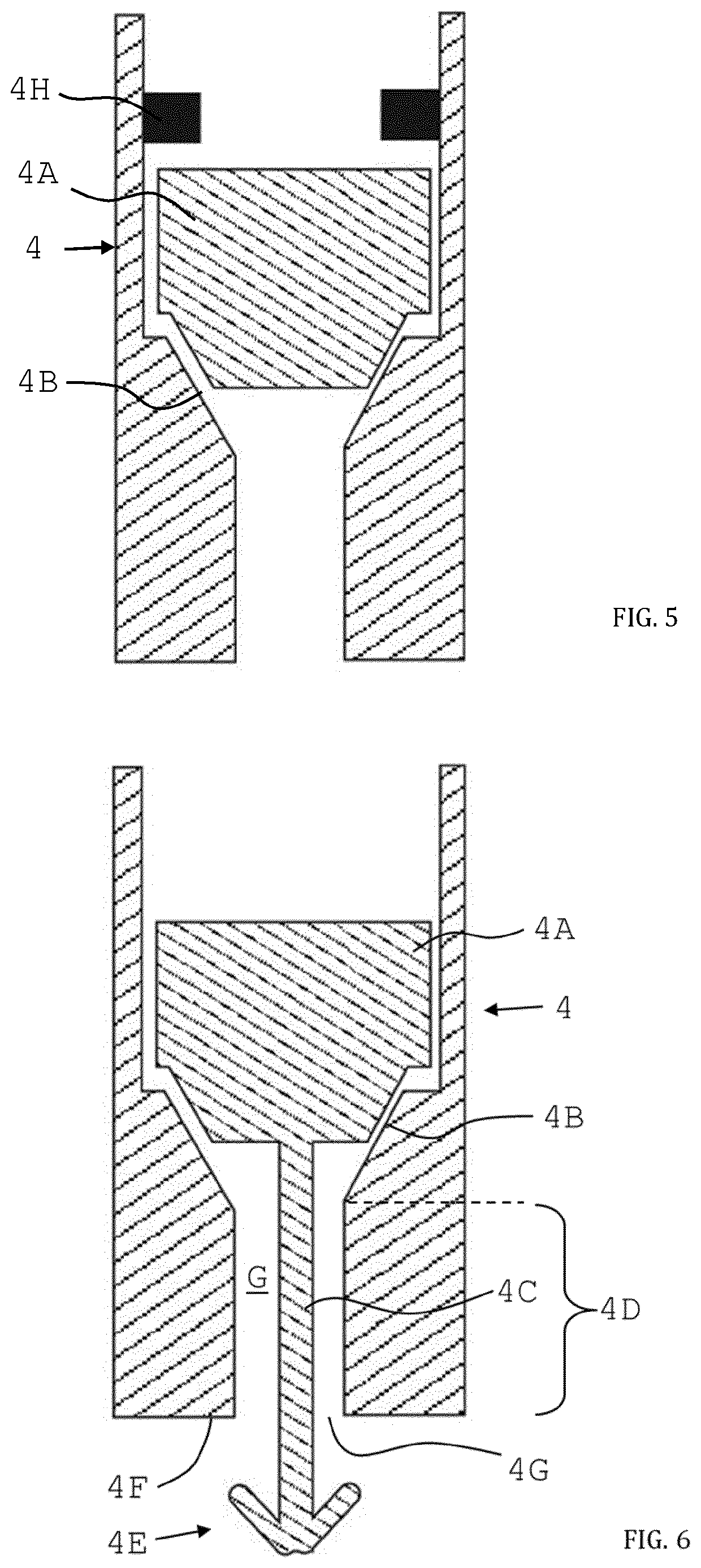
[0123]FIG. 6 shows a schematic of the cross section of a check valve comprised by the inhalation device according to the invention. In addition to the features known from the art and already shown in the previous figure, to the upstream side of body 4A, a protrusion 4C is attached.

[0124]Protrusion 4C extends in upstream direction towards the reservoir (not shown) through seat 4B, having an opening, and past an upstream arranged hollow seat extension section 4D having a downstream opening (no reference numeral) facing the, and being fluidically connected to, the seat 4B, and an upstream opening 4G arranged at the opposite, upstream end of the hollow seat extension region 4D. The protrusion 4C is dimensioned to leave a gap G between its lateral surface and the inside of hollow seat extension section 4D. Furthermore, upstream end 4E of protrusion 4C is configured to mechanically interact with an upstream end 4F of said hollow seat extension section 4D such as to being blocked from (re-...

second embodiment

[0126]In FIG. 7, a schematic of the cross section of a check valve 4 comprised by the inhalation device according to the invention is depicted. In this embodiment, the upstream end 4E of protrusion 4C receives a detachable ring-like structure 4I which increases the overall lateral size of upstream end 4E such that it is larger than the width of the upstream opening 4G. As a result, movement of protrusion 4C is blocked when ring-like structure 4I touches the upstream end 4F of hollow seat extension section 4D, and thus, valve body 4A is stopped from moving further away from seat 4B.

[0127]In FIG. 8, another embodiment of the check valve 4 to be comprised by the inhalation device of the present invention is schematically depicted. In this embodiment, the upstream end 4E of protrusion 4C is configured to provide a magnetic force, stemming from a first magnet 4J, which counteracts an accordingly dimensioned magnetic force arranged inside hollow seat extension section 4D at the upstream e...


PUM


Abstract

Inhalation device for generation of an aerosol of a medically active liquid, said inhalation device comprising a check valve (4); a housing (1), inside this housing (1) a reservoir (2) for storing said medically active liquid (L), downstream this reservoir (2) a pumping unit (3) for generation of a pressure connected to a means for the delivery of mechanical energy (6) to said pumping unit (3), and downstream said pumping unit (3) a nozzle (5); wherein the pumping unit (3) comprises a hollow cylindrical part (3A) and a piston (3B), the cylindrical part (3A) having an interior space (3C) configured to receive an end portion (3B′) of said piston (3B), wherein said cylindrical part (3A) and said piston (3B) are linearly moveable relative to one another such as to form a pumping chamber (3D) having a variable volume.

Description

FIELD OF THE INVENTION[0001]The invention relates to the field of inhalation devices for liquids. In particular, the invention relates to a pumping unit for an inhalation device having a piston which moves relative to a pumping chamber in order to generate pumping pressure.BACKGROUND OF THE INVENTION[0002]Nebulizers or other aerosol generators for liquids are known from the art since a long time ago. Amongst others, such devices are used in medical science and therapy. There, they serve as inhalation devices for the application of active ingredients in the form of aerosols, i.e. small liquid droplets embedded in a gas. Such an inhalation device is known e.g. from document EP 0 627 230 B1. Essential components of this inhalation device are a reservoir in which the liquid that is to be aerosolized is contained; a pumping unit for generation of a pressure being sufficiently high for nebulizing; as well as an atomizing device in the form of a nozzle. A pumping unit is defined as a unit,...

Claims


Application Information

Patent Timeline
IPC IPC(8): A61M11/00A61M15/00B05B11/00
CPCA61M11/007A61M15/0065A61M2205/0216B05B11/00412A61M2202/0468B05B11/3091A61P11/00B05B11/026B05B11/1091A61M2202/0007
Inventor BARTELS, FRANKRAWERT, JUERGEN
Owner SOFTHALE NV
Why Eureka
Try Eureka