
Apparatus for transferring linear loads

a linear actuator and actuator technology, applied in the direction of gearing, reciprocating combination engines, ways, etc., can solve the problems of undesirable wear and unusable movement of some parts of such machines

Active Publication Date: 2013-03-12
CATERPILLAR INC
View PDF15 Cites 12 Cited by
  • Summary
  • Abstract
  • Description
  • Claims
  • Application Information

AI Technical Summary

Problems solved by technology

Unfortunately, such vibrations of heavy-duty structures can result in undesirable movements of some parts of such machines relative to adjacent parts.
In particular, cylinder rods that may be utilized to rotate the eccentric weights relative to one another may have a tendency to rotate within their associated fixed cylinders, resulting in undesirable wear.

Method used


Image

  • Apparatus for transferring linear loads
  • Apparatus for transferring linear loads
  • Apparatus for transferring linear loads

Examples


Embodiment Construction

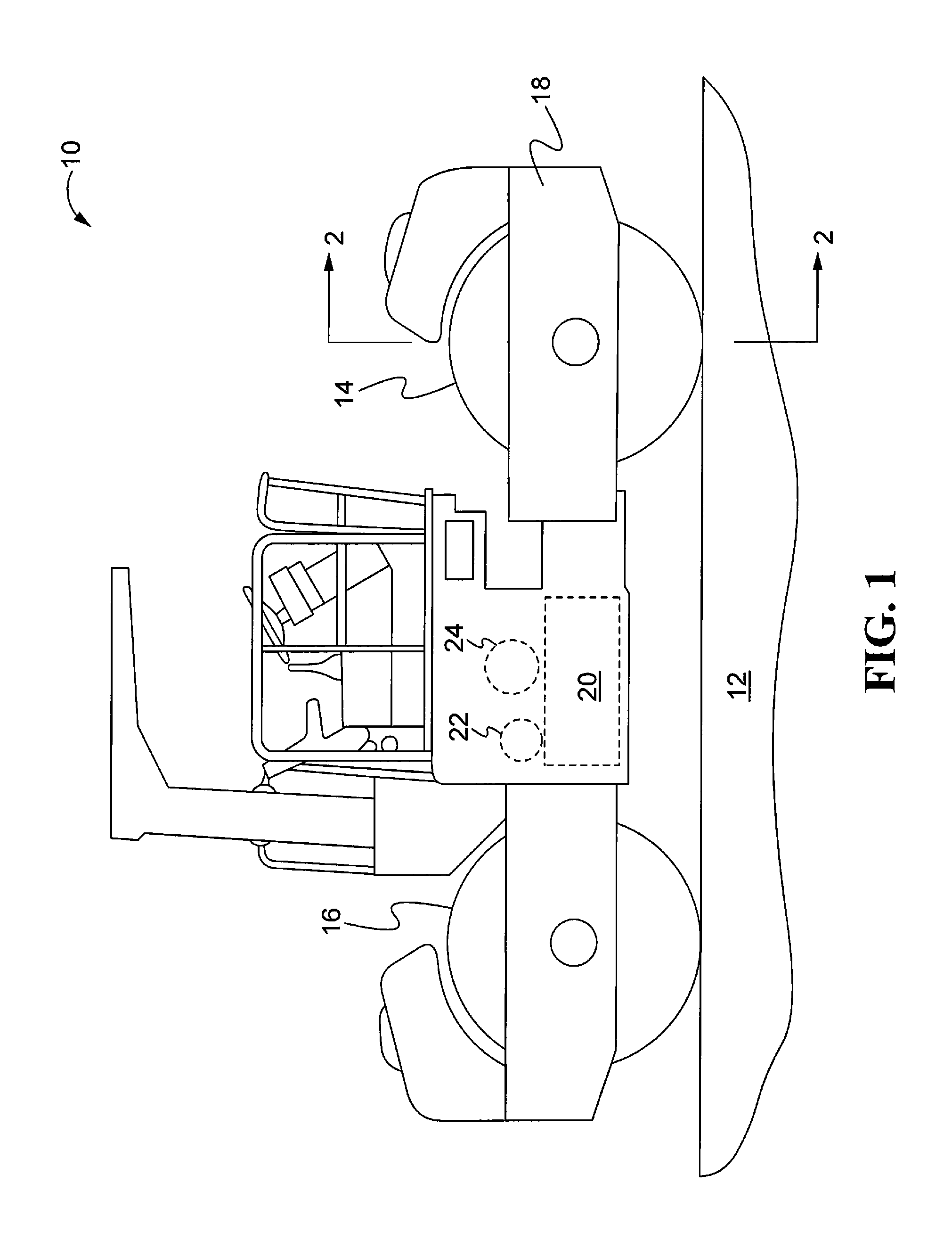
[0015]Making initial reference to FIG. 1, a double vibratory drum compaction machine 10 may be useful for compacting and / or increasing density of a compactable material or mat 12, such as soil, gravel, and / or bituminous mixtures. The machine 10 may have a front compacting drum 14 and a rear compacting drum 16, both rotatably mounted on a main frame 18. Although displayed herein as a double drum machine, the compactor 10 may alternatively utilize only a single vibratory drum without departing from the spirit and scope of the present disclosure. In the single vibratory drum machine, conventional wheels would be employed in lieu of the second drum for accommodating appropriate mobility of the machine 10.

[0016]The main frame 18 may also support an engine 20 (shown in phantom) for supplying motive power to the machine 10, as well as operating power to at least one electric generator 22 or fluid pump such as a variable displacement fluid pump 24 (both shown in phantom). To the extent that...


PUM

PropertyMeasurementUnit
speedaaaaaaaaaa
lengthaaaaaaaaaa
weightaaaaaaaaaa

Abstract

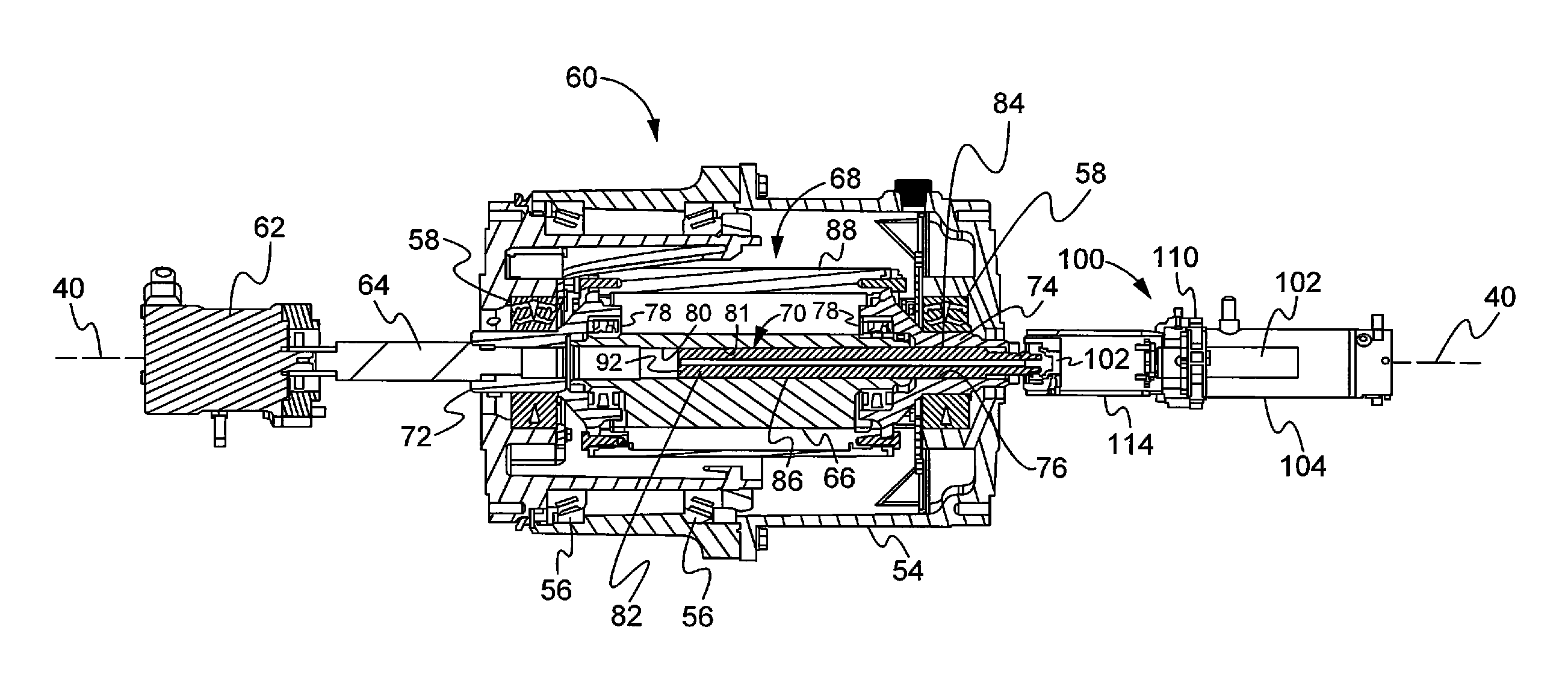
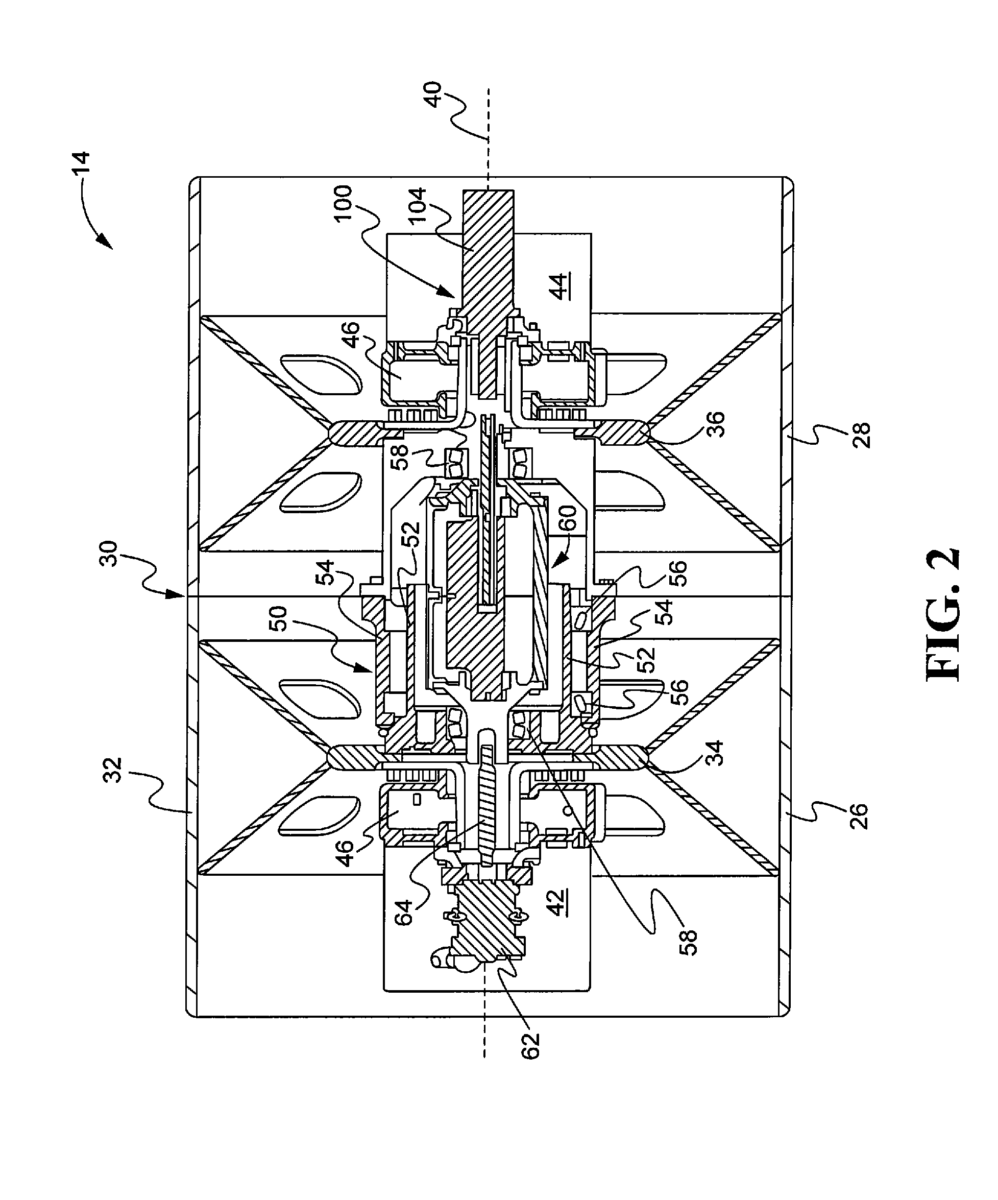
Apparatus for transferring a linear load through a high-speed rotating member includes a linear actuator containing an axially translatable cylinder rod. A mounting adapter fixed against axial and rotary movement is rigidly affixed to an actuator cylinder containing the cylinder rod. An elongate guide sleeve, fixed to the mounting adapter, extends axially from the adapter to accommodate an axially translatable thrust bearing affixed to one end of the cylinder rod. The guide sleeve contains a linear slot for accommodating a guide pin affixed to the thrust bearing housing, and transversely movable within the linear slot to prevent rotation of both bearing housing and cylinder rod components.

Description

RELATED U.S. APPLICATION DATA[0001]This application is related to U.S. application Ser. No. 12 / 962,758 entitled Vibratory System for a Compactor, filed Dec. 8, 2010.TECHNICAL FIELD OF THE DISCLOSURE[0002]The present disclosure relates to linear actuators adapted for transferring linear loads through high speed rotating members. More particularly, the disclosure relates to an apparatus for preventing undesirable rotation of an actuator cylinder rod in a compactor machine.BACKGROUND OF THE DISCLOSURE[0003]Compactor machines, also variously called compaction machines, are frequently employed for compacting fresh laid asphalt, dirt, gravel, and other compactable materials associated with road surfaces. One such type of compaction machine is a drum-type compactor having one or more drums adapted to compact particular material over which the compactor is being driven. In order to compact the material, the drum-type compactor includes a drum assembly having a vibratory mechanism that inclu...

Claims


Application Information

Patent Timeline
Patent Type & Authority Patents(United States)
IPC IPC(8): E01C19/38
CPCE01C19/286E01C19/282Y10T74/18344Y10T29/49826
Inventor MARSOLEK, JOHN L.OETKEN, NICHOLAS A.MASHEK, NATHAN L.HANSEN, ERIC A.
Owner CATERPILLAR INC
Learn More