Position sensor cord, position sensor and planar position sensor

a position sensor and position sensor technology, applied in resistors, resistor details, adjustable resistors, etc., can solve the problems of difficult to provide a long structure with the length of several meters or more, and fail to detect a position, etc., to achieve excellent flexibility, low mechanical strength, and long structure

Active Publication Date: 2013-03-12
HITACHI CABLE
View PDF10 Cites 5 Cited by
  • Summary
  • Abstract
  • Description
  • Claims
  • Application Information

AI Technical Summary

Benefits of technology

[0011]Accordingly, it is an object of the present invention to provide a position sensor cord, a position sensor and a planar position sensor, which are mountable to an uneven surface so that the degree of freedom of mount thereof is high, and which has a lengthy structure with a length of several meters or more.
[0048]The position sensor cord (i.e. a cord-type cable for a sensor for position detection) is a rubber or plastic-based cable with excellent flexibility, and is therefore mountable to an uneven surface. According to the first embodiment of the invention, since a linear insulator as a core member in the extrusion coating of the conductive layer, even the conductive rubber or conductive plastic with a low mechanical strength can be extrusion-coated over several meters or more, so that the position sensor cord has the lengthy structure.
[0049]According to the second embodiment of the invention, it is possible to avoid an excessive increase in the resistance of the position sensor cord, and therefore make the position sensor cord suitable for more elongation.

Problems solved by technology

However, a so-called “cord switch” (i.e. a cord-type cable having a switching function) for the pinch sensor disclosed by JP-A-2005-302736 detects only ON / OFF operation when a pressure is applied thereto, but fails to detect a position at which the pressure has is applied thereto by the object or person.
However, as to the position sensor having the aforementioned structure, there is a disadvantage in that it is difficult to provide the lengthy structure with the length of several meters or more.

Method used


Image

  • Position sensor cord, position sensor and planar position sensor
  • Position sensor cord, position sensor and planar position sensor
  • Position sensor cord, position sensor and planar position sensor

Examples


first embodiment

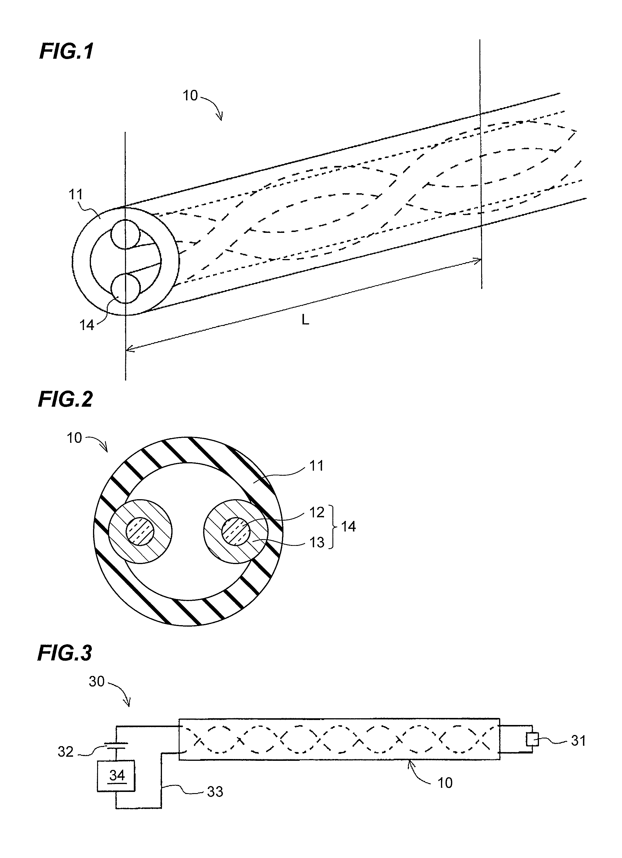
[0059]FIG. 1 is a perspective view showing a position sensor cord 10 in the first embodiment according to the invention, and FIG. 2 is a transverse cross sectional view thereof.

[0060]Herein, the so-called “position sensor cord” is a cord-type cable adapted for a position sensor. The position sensor is formed by using the position sensor cord.

[0061](Structure of a Position Sensor Cord 10)

[0062]Referring to FIGS. 1 and 2, the position sensor cord 10 in the first embodiment includes a hollow insulator 11 formed of a restorable rubber or a restorable plastic, and two linear resistive members 14 arranged in no electrical contact with each other and in a helical shape having a length L (e.g. L=5 to 6 mm) of one period in a longitudinal direction along an inner surface of the hollow insulator 11. Each linear resistive member 14 comprises a linear insulator 12 formed of an insulator, and an electrically conductive layer (hereinafter referred to as “conductive layer”) 13 provided around a ci...

second embodiment

[0079]A position sensor cord 10 in the second embodiment will be explained below.

[0080]The position sensor cord 10 in the first embodiment comprises the hollow insulator 11 and the two linear resistive members 14 arranged in the helical shape in the longitudinal direction along the inner surface of the hollow insulator 11.

[0081]The position sensor cord 10 in the second embodiment is similar to that in the first embodiment, except a linear conductive member 16 is used.

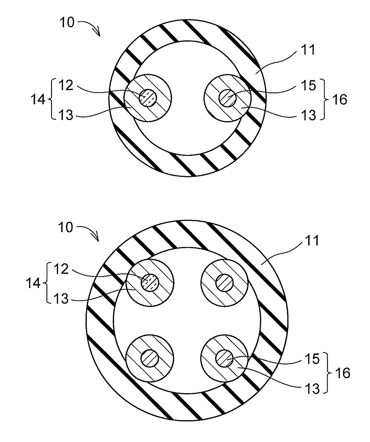
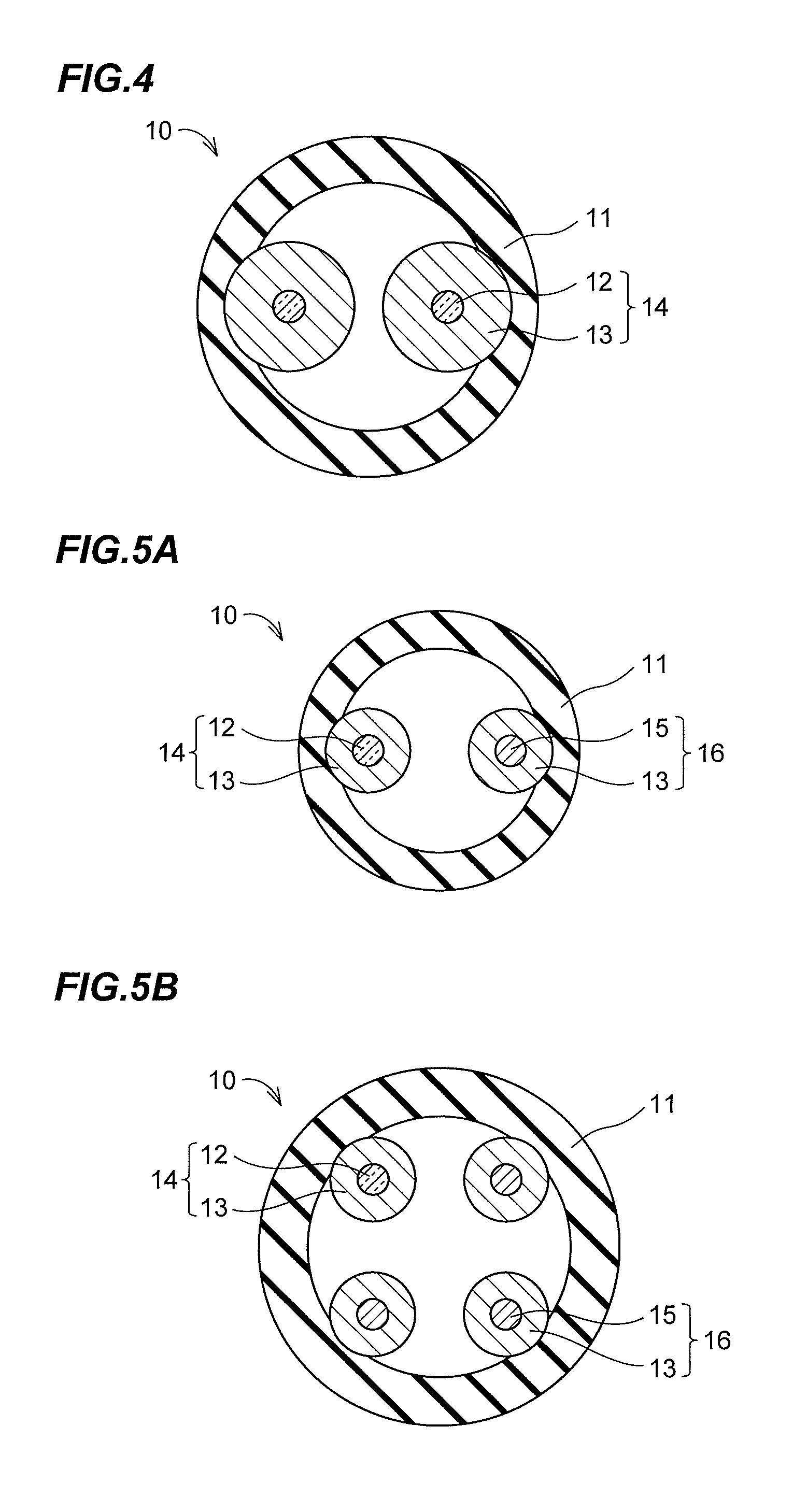
[0082]For example, as shown in FIG. 5A, one of the two linear resistive members 14 in the first embodiment is replaced with a linear conductive member 16 comprising a conductor 15 and the conductive layer 13 provided around the circumference of the conductor 15.

[0083]According to the structure as shown in FIG. 5A, since an excessive increase in the resistance of the position sensor cord 10 can be suppressed, it is possible to provide the position sensor cord 10 which is suitable for more elongation.

[0084]Referring to FI...

third embodiment

[0086]FIG. 6 shows a planar position sensor 50 in the third embodiment.

[0087](Planar Position Sensor 50)

[0088]Referring to FIG. 6, a planar position sensor 50 is formed by installing a plurality of the position sensors 30 in such a manner that the respective position sensor cords 10 are arranged in parallel to each other. According to this structure, it is possible to detect a schematic position in a plane P.

[0089]In the planar position sensor 50 (referred to as “the planar position sensor shown in FIG. 6”), the power supplies 32 and the resistance value detecting circuits 34 are converged on one end terminal 51. According to this structure, based on a variation in a resistance value of each position sensor cord 10, it is possible to detect the specific position sensor cord 10 to which the pressure is applied, and the position where the pressure is applied, thereby the schematic position thereof in the plane P.

[0090](Modification)

[0091]The planar position sensor 50 in the third embo...


PUM


Abstract

A position sensor cord includes a hollow insulator formed of a restorable rubber or a restorable plastic, and two linear resistive members. Each of the two linear resistive members includes a linear insulator and a conductive layer provided around a circumference of the linear insulator. The conductive layer is formed of a conductive rubber or a conductive plastic. The two linear resistive members are arranged in no electrical contact with each other and along an inner surface of the hollow insulator. One of the two linear resistive members may be replaced with one linear conductive member.

Description

[0001]The present application is based on Japanese patent application No. 2011-005000 filed on Jan. 13, 2011, the entire contents of which are incorporated herein by reference.BACKGROUND OF THE INVENTION[0002]1. Field of the Invention[0003]This invention relates to a position sensor cord, a position sensor and a planar position sensor.[0004]2. Description of the Related Art[0005]In general, a device for opening and closing a door or the like is mounted with a pinch sensor for detecting that an object, a person or the like (herein, referred to as “object or person”) is pinched or trapped in an opening and closing portion of the device. The pinch sensor is also called as foreign object detection sensor, anti-trap protection sensor, pressure sensor, or the like.[0006]This pinch sensor has been developed to be mountable to an uneven surface so that the degree of freedom of mount thereof is high, and to have a lengthy structure with a length of several meters or more.[0007]For example, J...

Claims


Application Information

Patent Timeline
Patent Type & Authority Patents(United States)
IPC IPC(8): H01C10/10
CPCH01C10/10H01C1/028
Inventor TANBA, AKIHIROAOYAMA, TAKASHI
Owner HITACHI CABLE
Why Eureka
Try Eureka