Lamp head assembly and lighting lamp tube

a technology of lamp head and lamp tube, which is applied in the direction of lighting and heating apparatus, semiconductor devices for light sources, lighting support devices, etc., can solve the problems of high power consumption, high heat generation, and quick attenuation

Active Publication Date: 2013-03-19
HARVATEK CORPORATION
View PDF3 Cites 41 Cited by
  • Summary
  • Abstract
  • Description
  • Claims
  • Application Information

AI Technical Summary

Benefits of technology

[0009]Therefore, the position of the inner head unit relative to the outer head unit or the position of the outer head unit relative to the inner head unit can be freely adjusted by selectively pressing, thus the light-projecting direction of the light-emitting assembly can be adjusted easily.

Problems solved by technology

However, compared to the newly developed light-emitting-diode (LED) lamps, these traditional lamps have the disadvantages of quick attenuation, high power consumption, high heat generation, short working life, high fragility, and being not recyclable.
However, conventional LED tubes suffer some drawbacks.
Therefore, without a specially designed rotatable mechanism, upon installation onto the bracket of a lamp device, the light-projecting angle of the conventional LED tube is fixed and can not be adjusted.
In other words, the electrode pins of the LED tube that electrically connect to the lamp bracket are fixed on two opposite ends of the LED tube, and thus when the electrode pins are inserted into the lamp bracket, the light beams generated by the LED tube is fixed and cannot be adjusted.
Moreover, if the hosting bracket of the lamp device is of incorrect alignment with respect to the illumination angle of the LED tube, a conventional LED tube structure is unable to provide adjustability for proper correction.
Therefore, the light-projecting angle of the prior art LED tubes cannot be corrected and cannot be adjusted according to the different requirements.

Method used


Image

  • Lamp head assembly and lighting lamp tube
  • Lamp head assembly and lighting lamp tube
  • Lamp head assembly and lighting lamp tube

Examples


Embodiment Construction

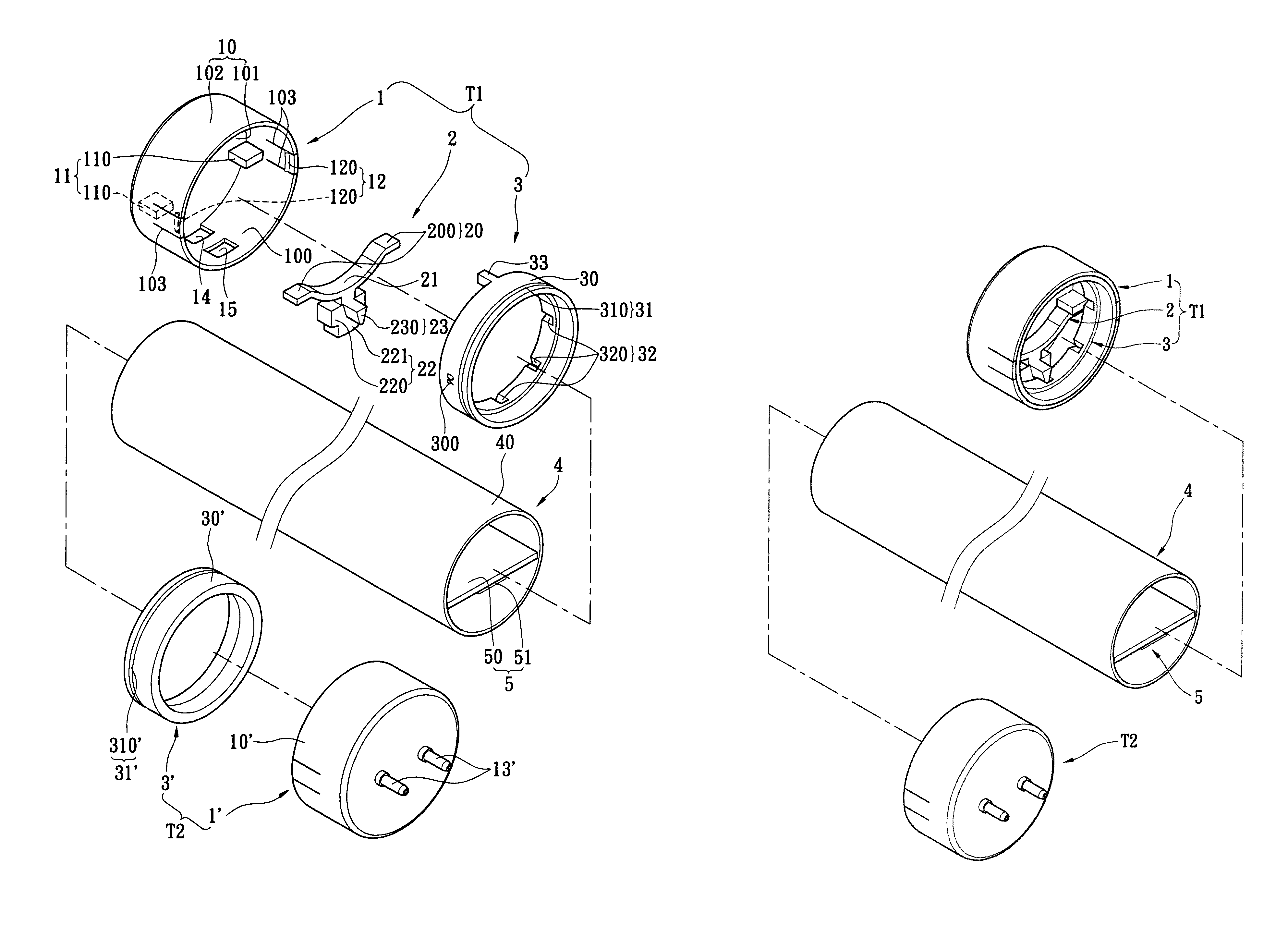
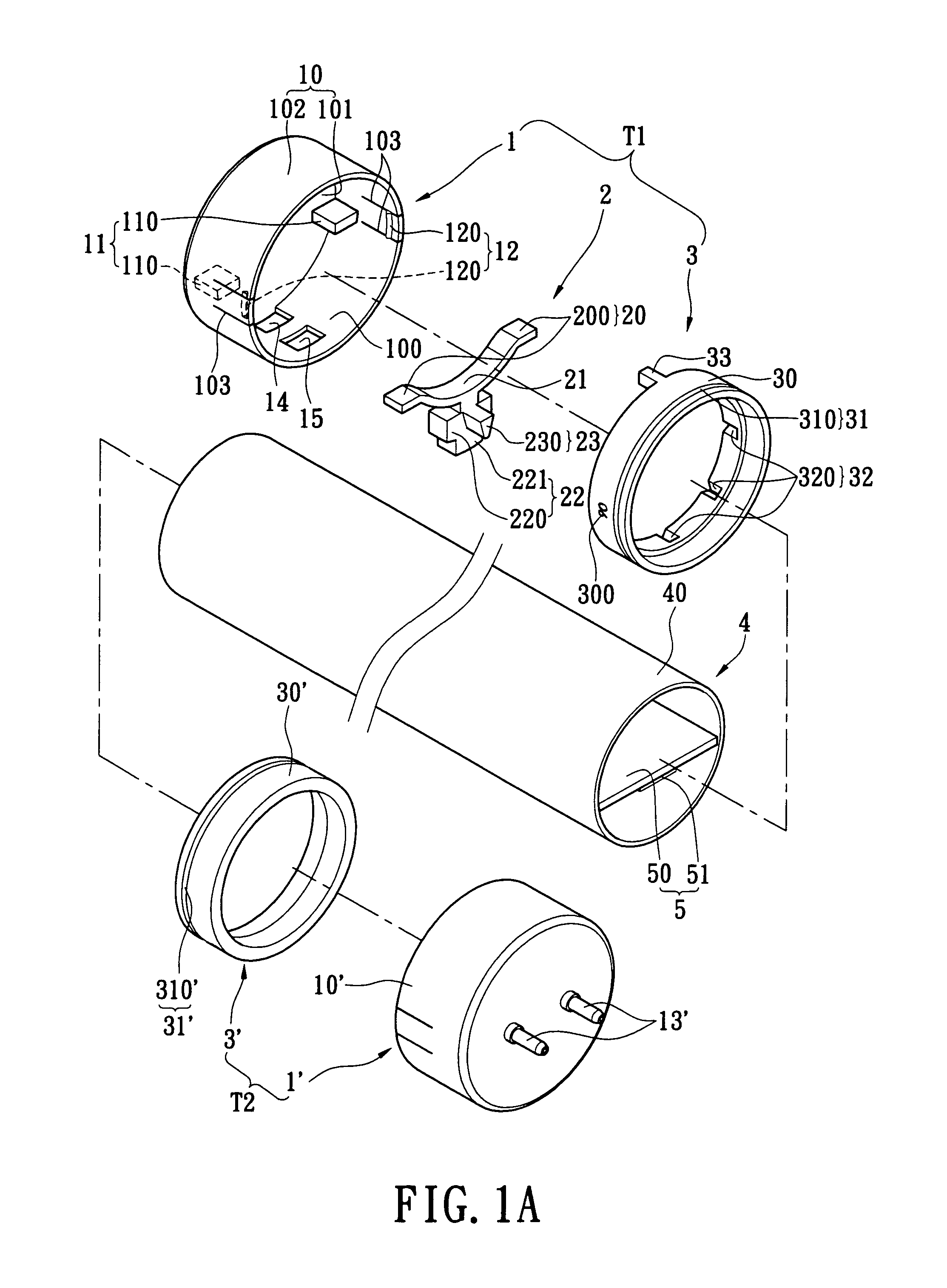
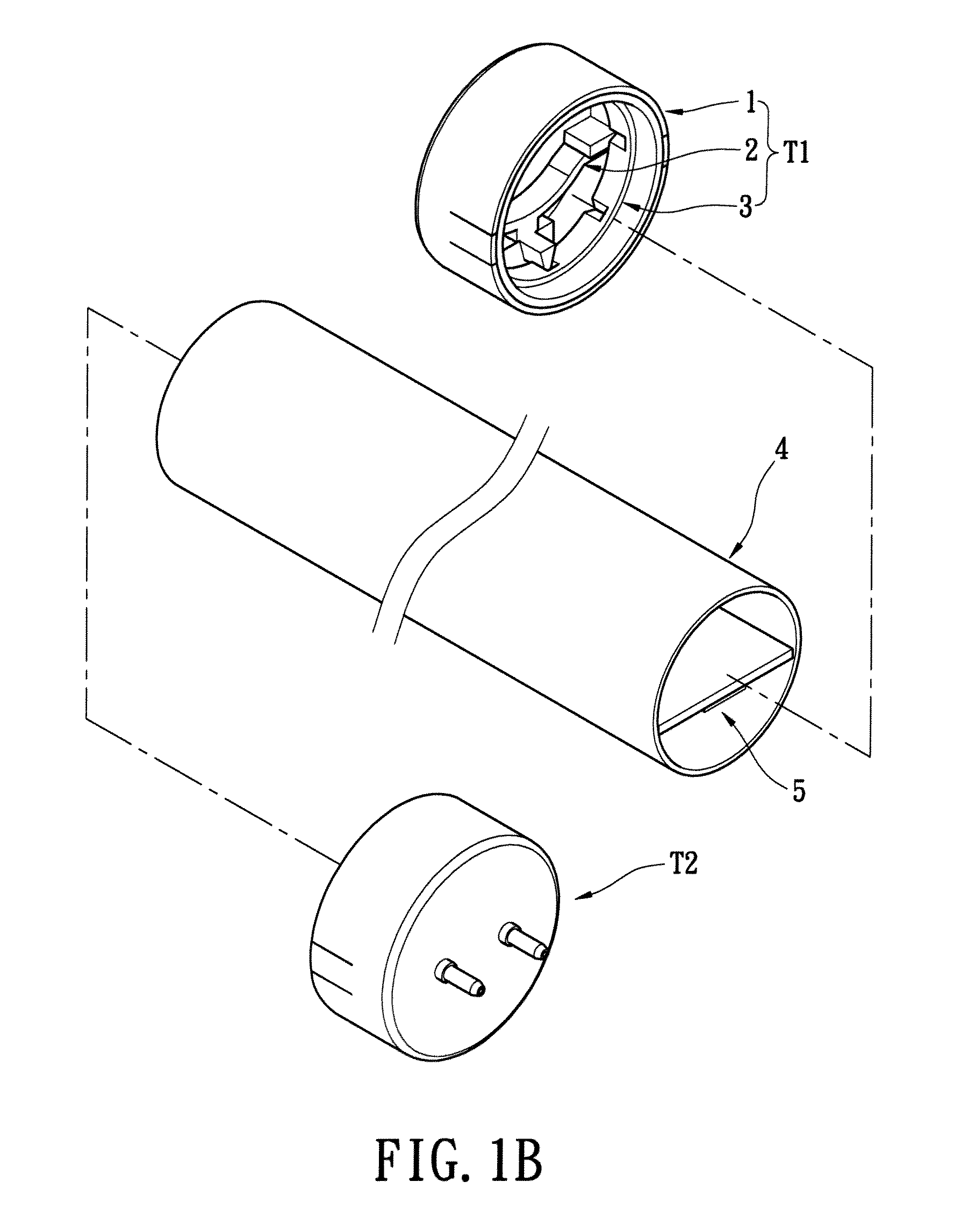
[0019]Referring to FIGS. 1A to 3, the first embodiment of the instant disclosure provides a lighting lamp tube for adjusting light-projecting direction by rotation motion, comprising: a lamp head assembly T1, an auxiliary lamp head assembly T2, a lamp assembly 4 and a light-emitting assembly 5, and the lamp head assembly T1 comprises an outer head unit 1, an elastic pressing unit 2 and an inner head unit 3.

[0020]The outer head unit 1 includes an outer head body 10, a first retaining structure 11 disposed on the inner surface of the outer head body 10, a first sliding structure 12 disposed on the inner surface of the outer head body 10, at least two conductive pins 13 passing through one side of the outer head body 10 and combined with the outer head body 10, and at least one button opening 14 passing through the outer head body 10. The outer head body 10 has a receiving groove 100. For example, the outer head body 10 has a lateral wall 101 and an annular wall 102 extended upwardly f...


PUM


Abstract

A lamp head assembly includes an outer head unit, an inner head unit, and an elastic pressing unit. The outer head unit includes at least two conductive pins. The inner head unit is disposed rotatably in the outer head unit. The elastic pressing unit is disposed movably in the outer head unit for selectively positioning the position of the inner head unit relative to the outer head unit or the position of the outer head unit relative to the inner head unit, wherein the elastic pressing unit includes a pressing element selectively exposed from the outer head unit.

Description

BACKGROUND OF THE INVENTION[0001]1. Field of the Invention[0002]The instant disclosure relates to a lamp head assembly and a lighting lamp tube, and more particularly, to a lamp head assembly and a lighting lamp tube for adjusting light-projecting direction by rotation motion.[0003]2. Description of Related Art[0004]Traditional lighting devices such as lamps that adopt incandescent bulbs, fluorescent bulbs, or power-saving bulbs have been generally well-developed and used intensively indoor illumination. However, compared to the newly developed light-emitting-diode (LED) lamps, these traditional lamps have the disadvantages of quick attenuation, high power consumption, high heat generation, short working life, high fragility, and being not recyclable. Thus, various high-powered LED lamps are created to replace the traditional lighting devices. Among them, tubular LED lamps are gaining popularity for their dimensional resemblance of traditional fluorescent tubes and thus their adopta...

Claims


Application Information

Patent Timeline
Patent Type & Authority Patents(United States)
IPC IPC(8): F21V19/02
CPCF21K9/17F21V21/30F21Y2101/02F21Y2103/003F21Y2103/10F21Y2115/10F21K9/272
Inventor WANG, BILYCHANG, CHI-TSENGLO, CHI-KANGFAN, ZHEN-HAO
Owner HARVATEK CORPORATION
Why Eureka
Try Eureka