Connector structure

a technology of connecting structure and connector, which is applied in the direction of coupling device connection, connection contact member material, coupling protective earth/shielding arrangement, etc., can solve the problems of ineffective prevention, inability to effectively prevent, and complicated structure of conventional electrical connector, etc., to achieve effective prevention of electromagnetic interference, simple structure, and easy assembly

Inactive Publication Date: 2013-03-19
ALL BEST ELECTRONICS
View PDF8 Cites 63 Cited by
  • Summary
  • Abstract
  • Description
  • Claims
  • Application Information

AI Technical Summary

Benefits of technology

[0006]A primary object of the present invention is to provide an improved connector structure that is simple in structure and easy to assemble, and includes ground units connected to a ground connecting member to enable effective prevention of electromagnetic interference during signal transmission at increased transmission rate.
[0015]With the above arrangements, the connector structure of the present invention is simple in structure and easy to assemble, and includes ground units all connected to a ground connecting member to enable effective prevention of electromagnetic interference during signal transmission at increased transmission rate.

Problems solved by technology

That is, the conventional electrical connector has the disadvantages of complicated structure and uneasy to assemble.
As a result, it is not able to effectively prevent electromagnetic interference when the electrical connector is used for signal transmission, and the transmission rate is adversely affected.

Method used


Image

  • Connector structure
  • Connector structure
  • Connector structure

Examples


Embodiment Construction

[0030]The present invention will now be described with some preferred embodiments thereof and with reference to the accompanying drawings.

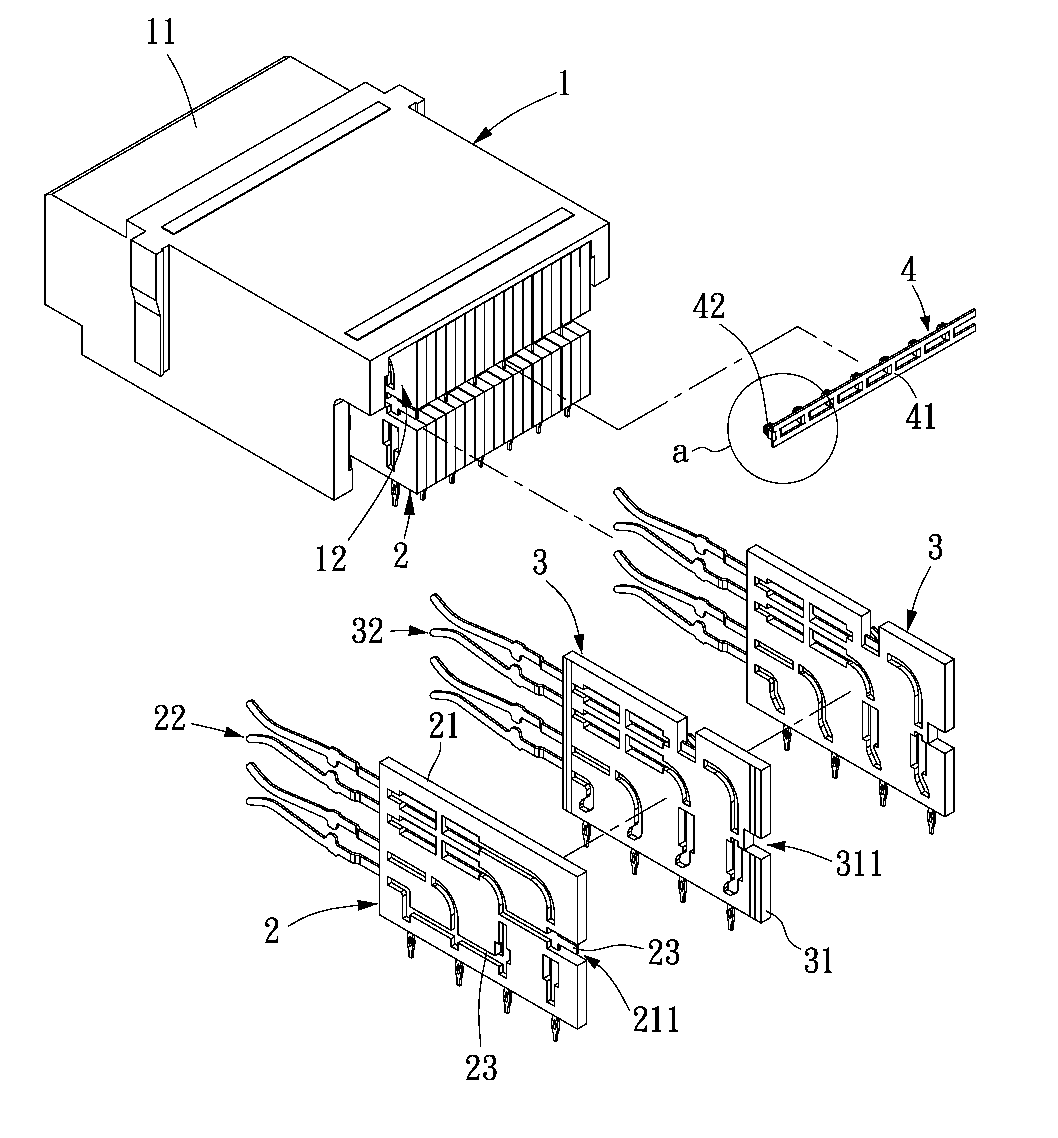
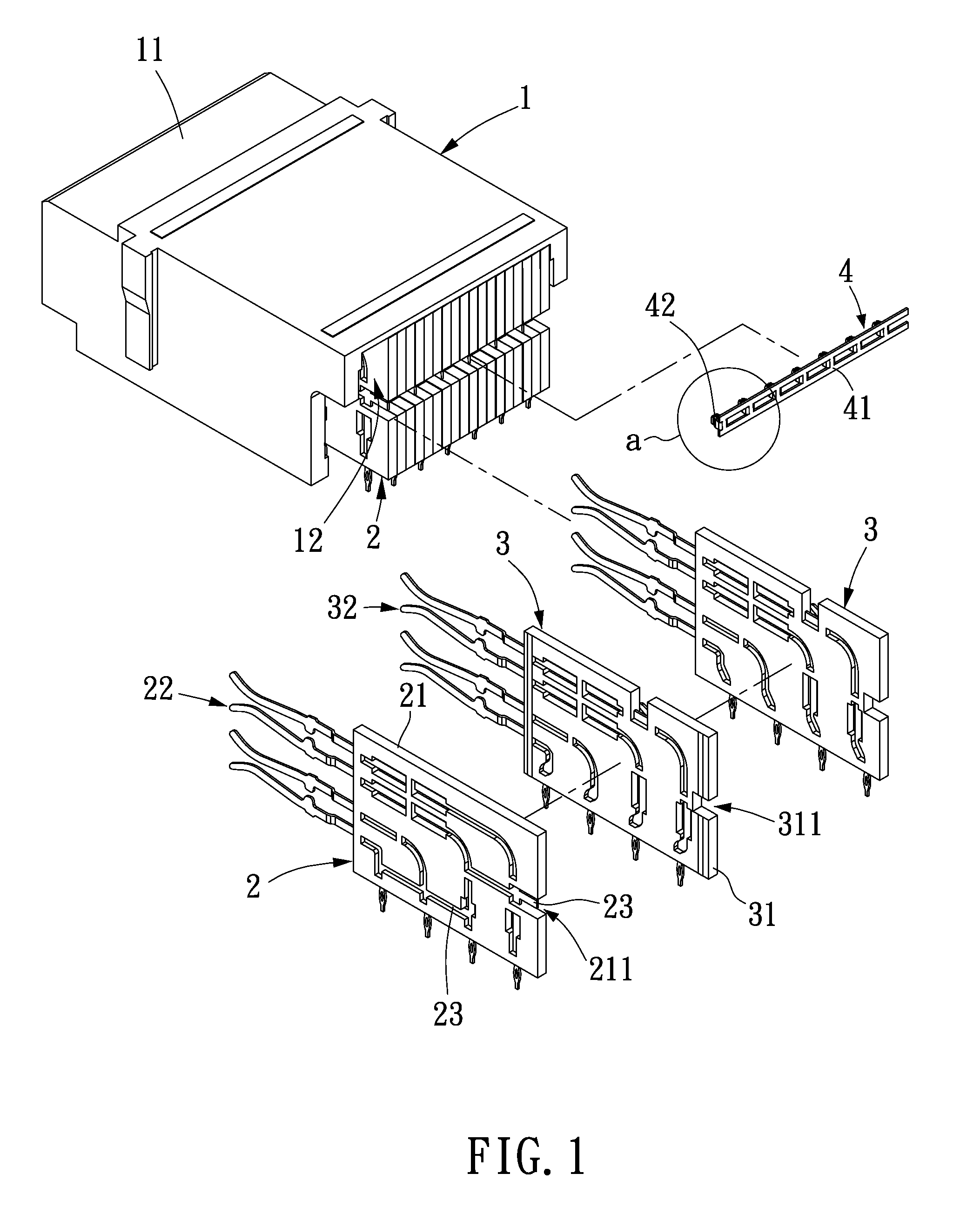
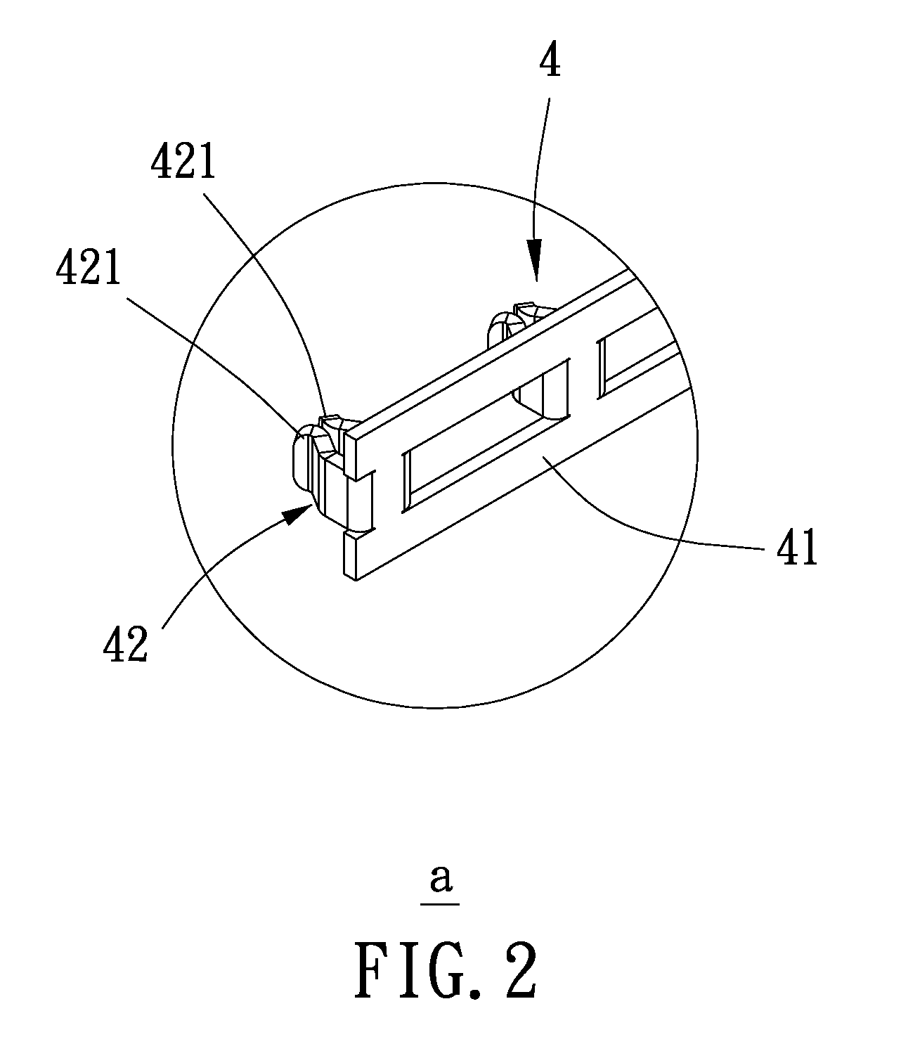
[0031]Please refer to FIGS. 1 through 6, in which FIGS. 1 and 3 are rear exploded and assembled perspective views, respectively, of a connector structure according to a first embodiment of the present invention, FIGS. 2 and 4 are enlarged views of the circled areas “a” and “b” in FIGS. 1 and 3, respectively, FIG. 5 is a front view of the connector structure of FIG. 3, and FIG. 6 is a sectional view taken along line A-A of FIG. 5. As shown, the connector structure in the first embodiment includes an enclosure 1, a plurality of grounding units 2, a plurality of signal units 3, and a ground connecting member 4.

[0032]The enclosure 1 has a front portion provided with a plug section 11 and an opposite rear portion internally defining a receiving space 12 communicating with the plug section 11.

[0033]The ground units 2 are arranged in the receiving space ...


PUM


Abstract

A connector structure includes an enclosure; a plurality of ground units arranged in the enclosure and respectively including a carrier plate and a plurality of ground terminals electrically connected to one another and associated with the carrier plate; a plurality of signal units arranged in the enclosure side by side to locate between any two adjacent ones of the ground units, and the signal units respectively including a carrier plate and a plurality of signal terminals associated with the carrier plate; and a ground connecting member connected to the carrier plates of the ground units and the signal units. With these arrangements, the connector has simple structure and can be easily assembled for use, and the ground units are connected to the ground connecting member to thereby effectively prevent electromagnetic interference during signal transmission and ensure increased transmission rate.

Description

FIELD OF TECHNOLOGY[0001]The present invention relates to a connector structure, and more particularly to a connector structure that is simple in structure and easy to assemble, and includes ground units connected to a ground connecting member to enable effective prevention of electromagnetic interference during signal transmission at increased transmission rate.BACKGROUND[0002]A conventional electrical connector, as shown in FIGS. 12 and 13, includes an enclosure 5; first and second terminal holders 6, 6a arranged in the enclosure 5 for supporting ground terminals 61; third and fourth terminal holders 7, 7a arranged in the enclosure 5 for supporting signal terminals 71; a plurality of pins 8 inserted into the enclosure 5 and extended through the terminal holders 6, 6a, 7, 7a to electrically connect to the ground terminals 61; and a plurality of conducting plates 9 connected to the ground terminals 61. With these arrangements, the electrical connector can be used for high-speed data...

Claims


Application Information

Patent Timeline
Patent Type & Authority Patents(United States)
IPC IPC(8): H01R13/648
CPCH01R13/6587H01R31/08
Inventor YANG, FENNY
Owner ALL BEST ELECTRONICS
Why Eureka
Try Eureka