
Electrode and arrangement with movable shield

a technology of movable shields and electrodes, applied in the direction of discharge tubes/lamp details, x-ray tubes, coatings, etc., can solve the problems of poor temperature conduction of electrodes, prior art solutions have disadvantages in terms of high constructive effort or other desired properties

Inactive Publication Date: 2013-03-19
APPLIED MATERIALS INC
View PDF14 Cites 0 Cited by
  • Summary
  • Abstract
  • Description
  • Claims
  • Application Information

AI Technical Summary

Benefits of technology

This patent is about an invention for a coating device that uses a special arrangement of electrodes to apply a coating called PECVD. The invention introduces a concept called an electric shield which helps to create a uniform coating. This shield is designed to restrict the space between the electrodes where the plasma is ignited for coating. The electric shield can be moved to adjust the electric field or potential distribution. This is especially useful when one electrode is designed to move, as it allows for easy adjustment. By setting the shield at earth potential, the coating process is improved. Additionally, the non-conducting formation of the shield helps to prevent discharge of electrically charged particles from the plasma.

Problems solved by technology

However, in connection with showerhead electrodes, problems arise, namely the provision of corresponding gas distribution spaces is observed to lead to poor temperature conduction in the electrode.
However, these prior art solutions have disadvantages in terms of a high constructive effort or other desired properties.

Method used


Image

  • Electrode and arrangement with movable shield
  • Electrode and arrangement with movable shield

Examples


Embodiment Construction

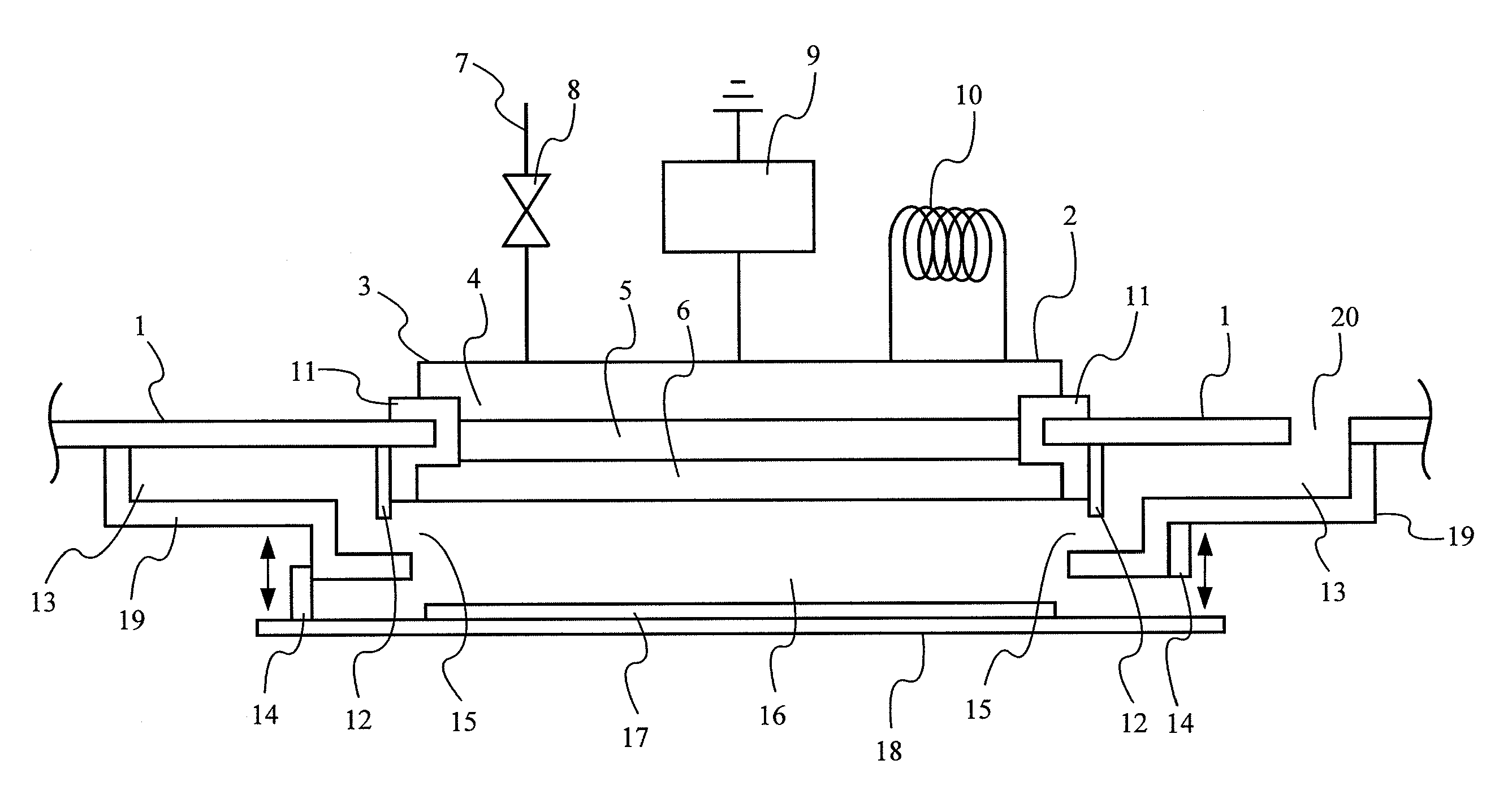
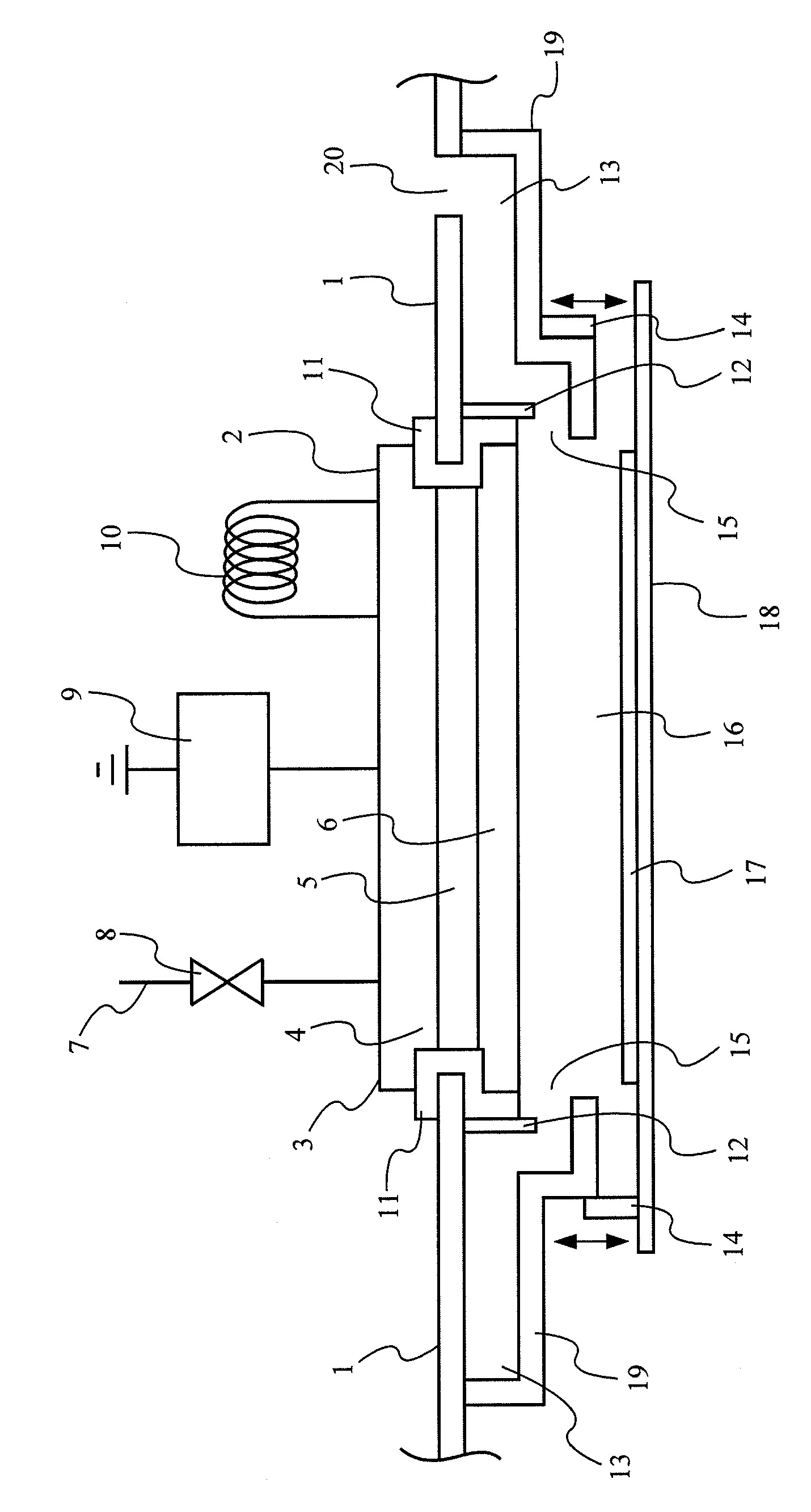
[0026]The enclosed drawing shows a part of a vacuum chamber wall 1, which has an electrode opening 2, in which a first electrode 3 is inserted.

[0027]The electrode 3 is made up of several plates 4 to 6 and accommodated via a peripheral seal or insulation 11 in the electrode opening 2 of the vacuum chamber wall 1.

[0028]Opposite electrode 3 is a counter-electrode 18, which also serves as a substrate carrier for a substrate to be coated 17. Whereas the electrode 3 arranged in the chamber wall 1 is connected to a high frequency or ultra-high frequency (HF / UHF) voltage source 9, which ensures that the electrode 3 is in contact with a high potential, the counter electrode 18 is set to earth potential (not shown).

[0029]In accordance with the horizontal double arrow drawn, the substrate carrier or the counter electrode 18 may be moved or displaced parallel to the principal surfaces of the electrodes 3 and 18 in order that the substrate to be coated 17 may be arranged opposite the electrode 3...


PUM

PropertyMeasurementUnit
conductiveaaaaaaaaaa
electrically non-conductingaaaaaaaaaa
shapeaaaaaaaaaa

Abstract

The present invention comprises an electrode arrangement for a coating device with a stationary first electrode (3) and a second movable electrode (18), whose principle surfaces are opposing each other during coating, wherein the second electrode (18) may be moved along a plane parallel to the opposing principle surfaces, wherein at least one end face of an electrode running transversely to the principal surface an electrical shield (12, 19, 13) is provided, which extends at least partially parallel to the end face of one electrode, wherein at least one part (14) of the shield is formed so as to be movable.

Description

BACKGROUND OF THE INVENTION[0001]1. Field of the Invention[0002]The present invention relates to an electrode arrangement for a coating device with a fixed first electrode and a second movable electrode, whose principle surfaces are opposite each other, wherein the second electrode may be moved along a plane parallel to the opposite principle surfaces.[0003]Moreover, the present invention relates to a corresponding coating device for use in plasma-enhanced chemical vapour phase deposition with a corresponding electrode arrangement.[0004]2. Prior Art[0005]Plasma enhanced chemical vapour deposition (PECVD) is known from the prior art and is widely employed in different applications for coating or modifying surfaces. For applications involving the coating of architectural glazing and also the manufacture of thin-layer solar cell modules, it is necessary to apply large-surface coatings of very high quality in terms of the homogeneity of the applied coating.[0006]To be able to effect a c...

Claims


Application Information

Patent Timeline
Patent Type & Authority Patents(United States)
IPC IPC(8): C23C16/50C23C16/00C23F1/00H01L21/306
CPCC23C16/5096H01J37/32082H01J37/32568H01J37/32623H01J37/32724H01J37/32761
Inventor STAHR, FRANKSTEPHAN, ULFSTEINKE, OLAFFSCHADE, KLAUS
Owner APPLIED MATERIALS INC
Learn More