Image capturing device, image capturing system, and method of driving image capturing device

a technology of image capturing and image signal, which is applied in the direction of color television details, television systems, radio control devices, etc., can solve the problems of deterioration in image quality of image obtained based on image signal, insufficient elimination, and inability to eliminate fixed pattern noise. , to achieve the effect of removing fixed pattern nois

Inactive Publication Date: 2013-03-19
CANON KK
View PDF22 Cites 67 Cited by
  • Summary
  • Abstract
  • Description
  • Claims
  • Application Information

AI Technical Summary

Benefits of technology

[0006]The present invention provides a technique useful in eliminating fixed pattern noise.

Problems solved by technology

In recent years, image capturing devices are increasingly required to attain higher performances, so increasing the number of pixels is a challenge of paramount importance in developing these devices.
If the differential amplifier cannot sufficiently eliminate the offset of the gain amplifier, an image signal in which fixed pattern noise remains is output, and this leads to deterioration in quality of an image obtained based on that image signal.
Also, when a subsequent stage of an image capturing device eliminates the offset of a gain amplifier, it may not be sufficiently eliminated if the offset level of the gain amplifier is relatively high.
In this case as well, an image in which fixed pattern noise remains is output, and this leads to deterioration in quality of an image obtained based on that image signal.

Method used


Image

  • Image capturing device, image capturing system, and method of driving image capturing device
  • Image capturing device, image capturing system, and method of driving image capturing device
  • Image capturing device, image capturing system, and method of driving image capturing device

Examples


first embodiment

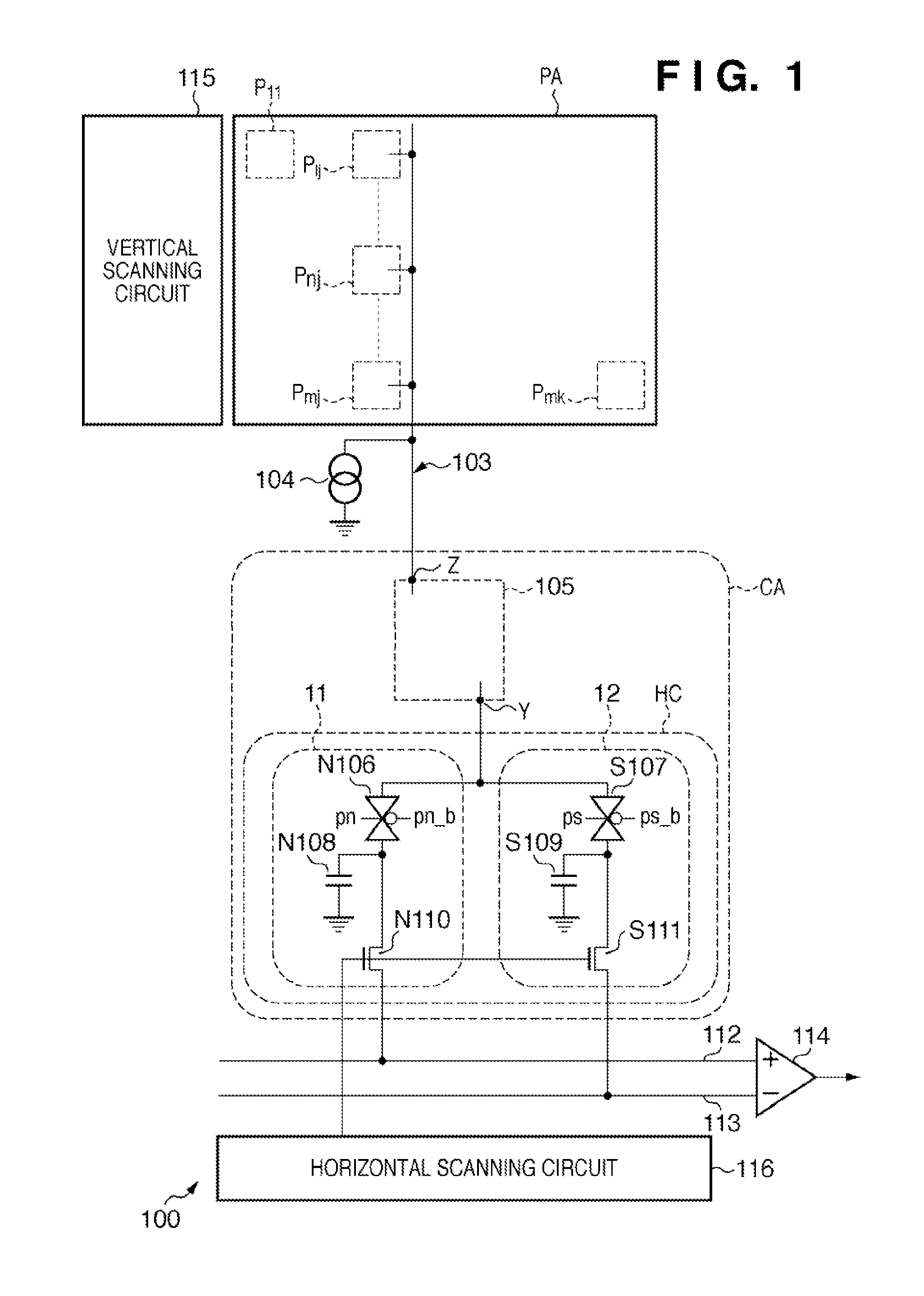
[0016]An image capturing device 100 according to the first embodiment of the present invention will be explained with reference to FIGS. 1 to 4. FIG. 1 is a block diagram showing the arrangement of the image capturing device 100 according to the first embodiment.

[0017]The image capturing device 100 includes a pixel array PA, a plurality of signal lines 103 (only one signal line 103 is shown in FIG. 1), a vertical scanning circuit 115, a plurality of column amplifier units CA (only one column amplifier unit CA is shown in FIG. 1), a horizontal scanning circuit 116, and an output amplifier 114.

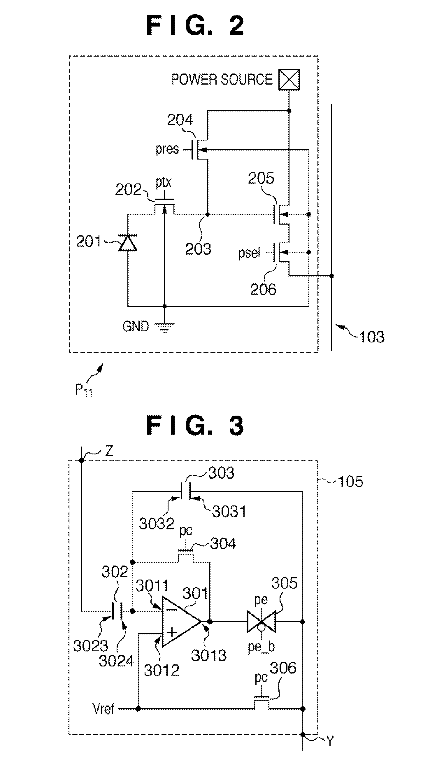
[0018]In the pixel array PA, a plurality of pixels P11, . . . , P1j, . . . , Pnj, . . . , Pmj, . . . , Pmk are one- or two-dimensionally arrayed. FIG. 1 illustrates the structure of the pixel array PA in which a plurality of pixels are two-dimensionally arrayed. The pixel P11 includes a photoelectric conversion portion 201, transfer portion 202, charge-voltage converter 203, reset portion 204, o...

second embodiment

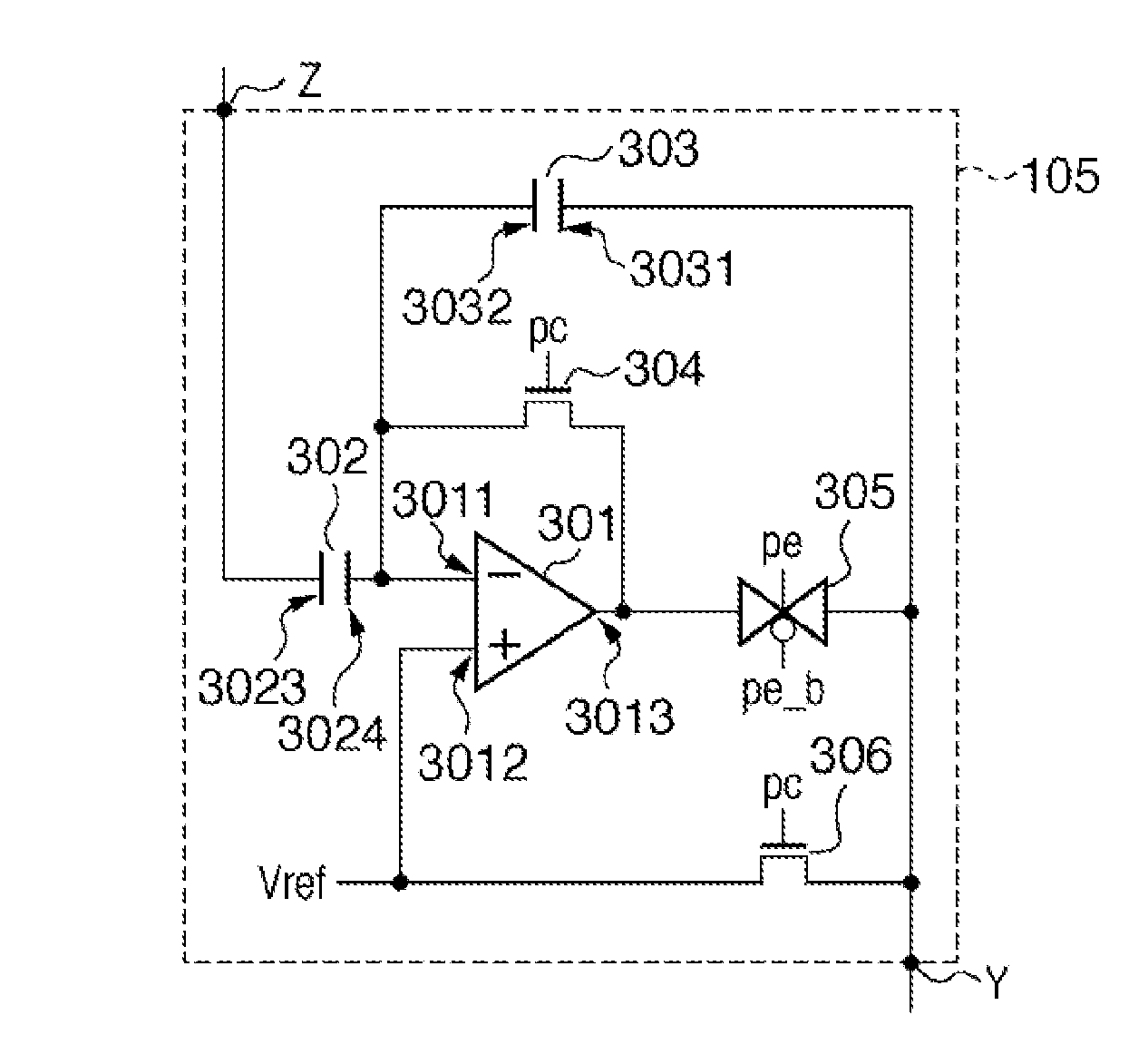
[0057]The second embodiment will be explained next. The first embodiment exemplified a case in which an operational amplifier is adopted as the column amplifier 105. The second embodiment will exemplify a case in which an inverting amplifier, especially a common-source circuit is adopted in place of an operational amplifier.

[0058]FIG. 6 shows a column amplifier 105 in the second embodiment of the present invention. The same reference numerals as in the first embodiment denote parts having the same functions in FIG. 6, and a detailed description thereof will not be given. The differences from the first embodiment reside in that a switch (third switch) 606 for supplying VREF is used, and the amplifier used is changed from the operational amplifier 301 to an inverting amplifier 601. The inverting amplifier 601 includes an input terminal (second input terminal) 3011′ and output terminal (second output terminal) 3013. Variations of the inverting amplifier 601 will be explained with refer...


PUM


Abstract

An image capturing device comprises a pixel array having a plurality of pixels each including a photoelectric conversion portion, a plurality of signal lines connected to the pixel array, a plurality of column amplifiers configured to respectively amplify signals transferred from the pixel array via the signal lines, the column amplifier comprising a first input terminal, a first output terminal, an amplifier having a second input terminal and a second output terminal, a feedback capacitance arranged between the second input terminal and the first output terminal, an input capacitance having an electrode connected to the first input terminal, and an electrode connected to the second input terminal, a first switch arranged between the second input terminal and the second output terminal, a second switch arranged between the first output terminal and the second output terminal, and a third switch arranged between a reference voltage terminal and the first output terminal.

Description

TECHNICAL FIELD[0001]The present invention relates to an image capturing device, an image capturing system, and a method of driving the image capturing device.BACKGROUND ART[0002]Japanese Patent Laid-Open No. 2003-051989 describes a method of amplifying, by a gain amplifier 41 in each column, signals output from the pixels in the column in a pixel array in which a plurality of pixels are two-dimensionally arrayed. When a MOS switch 54 is ON, the gain amplifier 41 operates as a voltage follower to initialize an inverting input portion 48. A pulse synchronous with that applied to a supply terminal 45 is applied to a supply terminal 58 to match the potential of an output portion 51 with the one obtained by adding the offset voltage of the gain amplifier 41 to the potential of a non-inverting input portion 47, thereby storing the offset of the gain amplifier 41 in a capacitance 23. A pulse applied to a pulse terminal 14 is set to high level to transfer an optical signal generated by a p...

Claims


Application Information

Patent Timeline
Patent Type & Authority Patents(United States)
IPC IPC(8): H04N5/335H01L27/146H04N5/357H04N5/365H04N5/369H04N5/374H04N5/376
CPCH04N3/1568H04N5/335H04N5/3658H04N5/378H04N25/677H04N25/75
Inventor ITANO, TETSUYAIIDA, SATOKOTAKAHASHI, HIDEKAZUYOSHIDA, DAISUKE
Owner CANON KK
Why Eureka
Try Eureka