Medical X-ray CT imaging apparatus

a technology of ct imaging and x-ray, which is applied in the direction of tomography, patient positioning for diagnostics, instruments, etc., can solve the problems of not being able to support efficient diagnoses or effective explanations for patients, and achieve good visibility

Active Publication Date: 2013-03-19
MORITA MFG CO LTD
View PDF19 Cites 9 Cited by
  • Summary
  • Abstract
  • Description
  • Claims
  • Application Information

AI Technical Summary

Benefits of technology

[0007]Since the CT imaging can be automatically performed consecutively on the imaging regions specified for both the first living organ and the second living organ, the operational load of an operator can be reduced. The medical X-ray CT imaging apparatus according to the present invention can be configured to perform local CT imaging on only part of the subject as the imaging region, and it is therefore possible to reduce the radiation exposure dose for the respective imaging regions of the first living organ and the second living organ and perform X-ray CT imaging with high resolution. Further, the medical X-ray CT imaging apparatus according to claim 1 of the present invention may have such a size as to occupy the same area as that of the conventional dental panoramic radiography apparatus and as to be housed in an X-ray proof chamber of a dental clinic or the like.
[0035]Since the first living organ, the second living organ, and the third living organ are displayed in accordance with the actual arrangement, good visibility can be achieved for recognition of the positions of these three living organs.

Problems solved by technology

Further, in order to compare the CT images of the living organs which are symmetrically located with respect to a predetermined plane with each other, the conventional medical X-ray CT imaging apparatuses require operator's operation for displaying the CT images for comparison and therefore cannot support efficient diagnoses or effective explanations for patients.

Method used


Image

  • Medical X-ray CT imaging apparatus
  • Medical X-ray CT imaging apparatus
  • Medical X-ray CT imaging apparatus

Examples


example 4

[0137] the CT imaging on the imaging region rc, the CT imaging on the imaging region rl, and the CT imaging on the imaging region rr,

[0138]Example 5: the CT imaging on the imaging region rr, the CT imaging on the imaging region rc, and the CT imaging on the imaging region rl, and

[0139]Example 6: the CT imaging on the imaging region rl, the CT imaging on the imaging region rc, and the CT imaging on the imaging region rr.

[0140]Herein, it is assumed that one of the right-side living organ or and the left-side living organ of is the first living organ, the other is the second living organ, and the central living organ oc is the third living organ.

[0141]In Examples 1 and 2, the CT imaging on the third living organ is performed after the serial CT imaging on the first living organ and the second living organ.

[0142]In Examples 3 and 4, the CT imaging on the third living organ is performed before the serial CT imaging on the first living organ and the second living organ.

[0143]In Examples 5...


PUM


Abstract

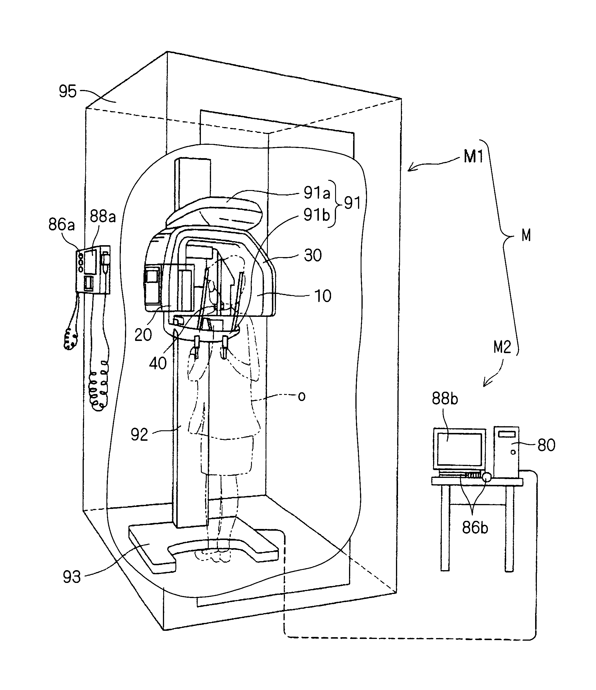
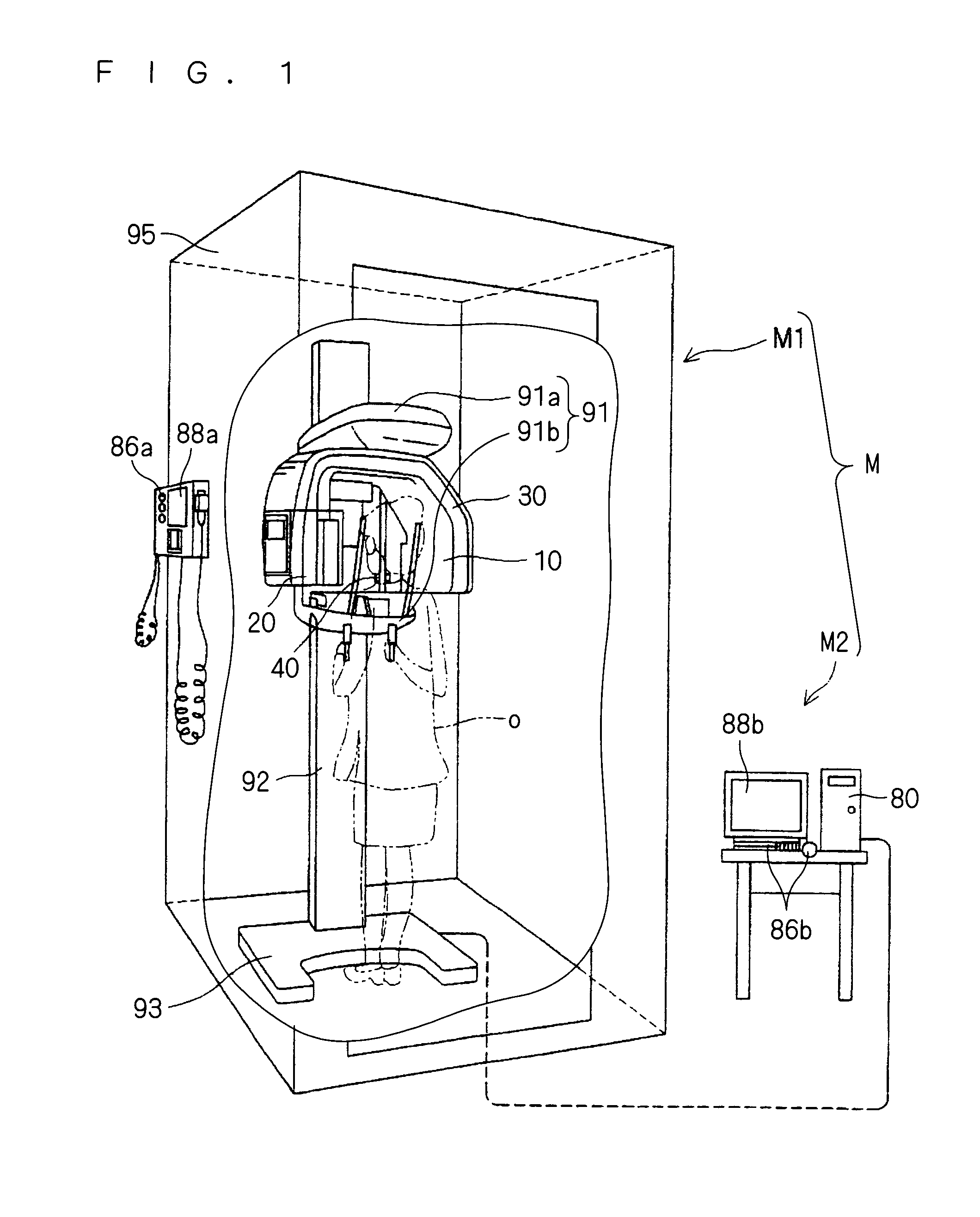
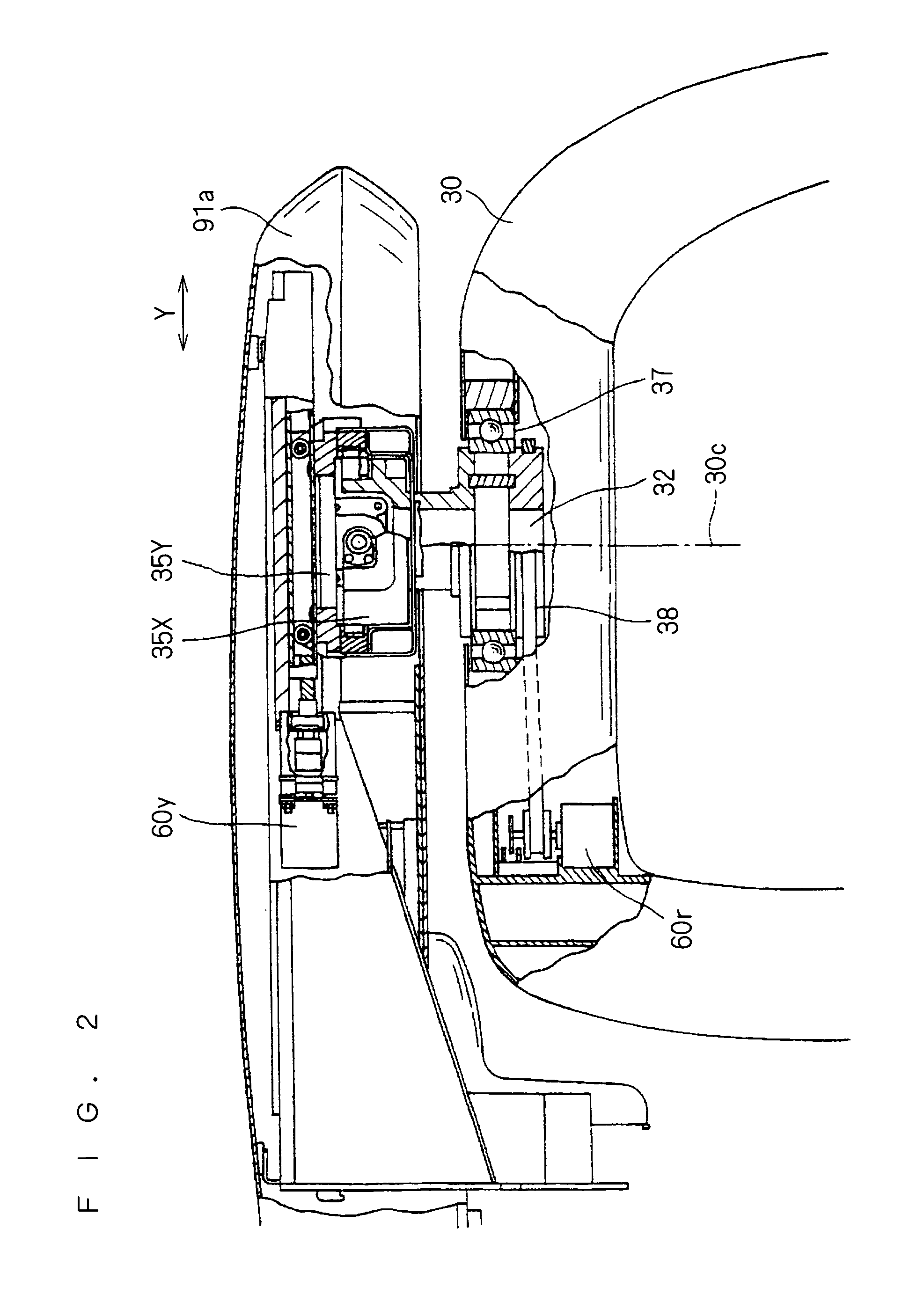
A medical X-ray CT imaging apparatus is capable of performing efficient CT imaging of living organs symmetrically located with respect to a predetermined plane. The medical X-ray CT imaging apparatus comprises an X-ray source (10), an X-ray detection means (20), a supporting means (30), a subject holding means (40), a rotation means (60r), a moving means (60), an imaging region specifying means for specifying imaging regions of a first living organ and a second living organ which are symmetrically located with respect to a predetermined plane, a calculation means which uses the moving means (60) and the rotation means (60r) to automatically and consecutively perform X-ray CT imaging of respective imaging regions of the first living organ and the second living organ, which are specified by the imaging region specifying means, and reconstructs respective CT images of the first living organ and the second living organ on the basis of electrical signals obtained by the X-ray CT imaging, and a display part (88) for displaying the CT images of the first living organ and the second living organ, which are obtained by the calculation means.

Description

TECHNICAL FIELD[0001]The present invention relates to a medical X-ray CT imaging apparatus, and more particularly to a medical X-ray CT imaging apparatus for performing CT imaging of living organs located symmetrically with respect to a predetermined plane.BACKGROUND ART[0002]In recent years, the development of medical X-ray CT imaging apparatuses has advanced and many apparatuses having provisions for imaging in dentistry or imaging of head including otolaryngological regions and the like have been developed and manufactured. In the field of dental X-ray CT imaging apparatus, apparatuses for combined use of not only CT imaging but also panoramic radiography (disclosed in e.g., Japanese Patent No. 3807833) have been developed. Japanese Patent Application Laid-Open Gazette No. 54-113292 discloses an example of old-type medical X-ray CT imaging apparatus which performs film radiography. The medical X-ray imaging apparatus disclosed in Japanese Patent Application Laid-Open Gazette No. ...

Claims


Application Information

Patent Timeline
Patent Type & Authority Patents(United States)
IPC IPC(8): G06K9/00
CPCA61B6/032A61B6/14A61B6/4441A61B6/04A61B6/545
Inventor NAKAI, TERUJIYASUDA, KOUJIITO, TETSUZO
Owner MORITA MFG CO LTD
Why Eureka
Try Eureka