
Robot, and control apparatus, control method, and control program for robot

a robot and control apparatus technology, applied in the direction of program control, electric programme control, instruments, etc., can solve the problems of inability to apply to a general household environment, device becomes bulky and heavier, and degrade work efficiency, etc., to achieve easy use of robots, simple and light weighted structures, and high degree of freedom

Active Publication Date: 2013-03-19
PANASONIC CORP
View PDF26 Cites 14 Cited by
  • Summary
  • Abstract
  • Description
  • Claims
  • Application Information

AI Technical Summary

Benefits of technology

The present invention is for a robot that includes a joint lock mechanism and a waist mechanism. The joint lock mechanism allows the robot to hold weight and maintain a stable position, while the waist mechanism allows for lifting of heavy objects. The robot can switch between an impedance control mode and a position control mode, and can easily control the position and operation of the arm and heavy objects. The control apparatus and method for the robot provide intuitive operation controls and allow for continuous operations, making the robot more easily usable. The technical effects of the present invention are a light weighted arm and a high-power robot that is simple and easy to use.

Problems solved by technology

However, the conventional device disclosed in Patent Document 1 has an issue that, since manual operations are required, operability is poor to cause degradation of work efficiency.
Moreover, even when an actuator such as a motor is added to provide automatic operations for improvement of the work efficiency, the device becomes bulky and heavier, thereby failing to be applied to a general household environment.
Moreover, in the conventional device disclosed in Patent Document 2, since the position of a care giver, that is an operator, is limited to a chair of the device, and since, upon a lift-up operation, hands of the care giver are located beneath the cared person and unable to move freely, it is not possible to carry out another job simultaneously for example, thereby failing to provide usability.

Method used


Image

  • Robot, and control apparatus, control method, and control program for robot
  • Robot, and control apparatus, control method, and control program for robot
  • Robot, and control apparatus, control method, and control program for robot

Examples


embodiment 1

(Embodiment 1)

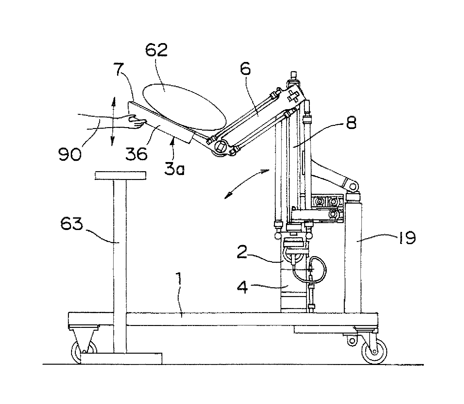
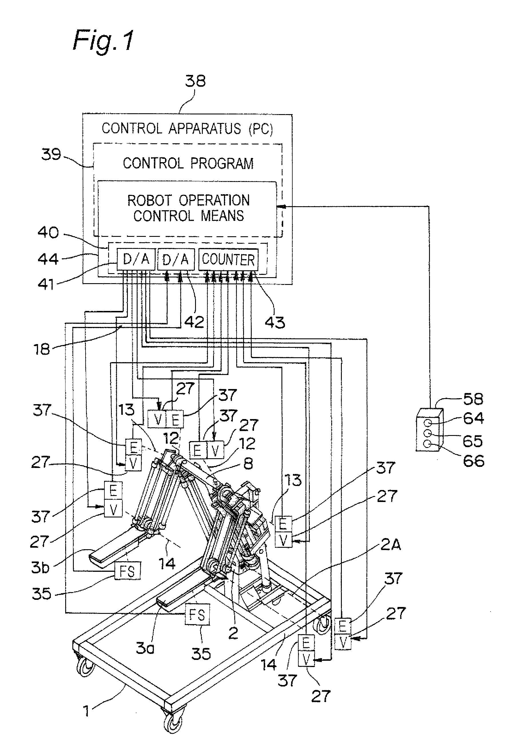
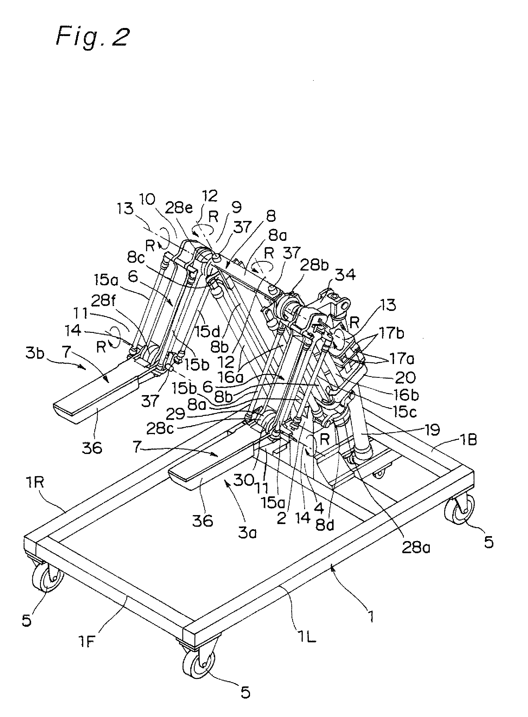
[0092]FIG. 1 is a view that shows a schematic structure of a robot according to a first embodiment of the present invention. FIG. 2 is a perspective view that shows a mechanical structure of the robot. FIG. 3 is a side view of the robot.

[0093]The robot is composed of five blocks, namely, a base unit 1 having a rectangular frame shape, a waist mechanism 2 that functions as one example of a body unit moving mechanism secured to the base unit 1, a body unit 8 supported by the waist mechanism 2, a left arm 3a supported on the left side of the body unit 8, and a right arm 3b supported on the right side of the body unit 8.

[0094]On the upper surface of the base unit 1 forming a base of the robot, a rectangular parallelepiped strut 4 is placed, and the waist mechanism 2 is placed on the upper portion of the strut 4. Moreover, wheels 5 are placed at four corners of the base unit 1 respectively so that the entire robot is movable.

[0095]The waist mechanism 2 is composed of rotati...


PUM


Abstract

A robot arm provided with a body unit shifting mechanism that connects a base unit and a body unit so as to be relatively shifted, and joint lock mechanisms that are capable of mechanically securing respective joints is disposed on the body unit, and a robot operation control unit controls to switch between a robot arm operation mode in which the robot arm is operated with one of the joints of the robot arm brought into a free state, and a body unit shift mode in which the body unit is shifted with the joint being brought into a locked state.

Description

TECHNICAL FIELD[0001]The present invention relates to a robot that carries out a lift-up operation of a heavy object, such as a lift-up job in nursing care or a transporting operation of an article, or a transporting operation or the like, as well as a control apparatus, a control method, and a control program for such a robot.BACKGROUND ART[0002]In the recent aged society, there have been demands for development of an apparatus capable of giving an assist, such as nursing care, or a power assist apparatus or the like used for assisting an elder person to carry out a house-keeping job.[0003]In view of these demands, there has been disclosed, as a conventional technique, a movable lift for nursing care, which is movable even in a narrow passage without requiring much labor of a care giver, and usable and available even in a small-size facility in a simple structure at low costs (see Patent Document 1). Moreover, there has been disclosed a transfer-lifting machine, composed of lift-up...

Claims


Application Information

Patent Timeline
Patent Type & Authority Patents(United States)
IPC IPC(8): G05B19/18G05B19/00
CPCA61G7/1017A61G7/1057A61G7/1065B25J5/007B25J9/0084B25J9/0087B25J9/1075B25J9/142B25J13/085B25J19/0004A61G7/1046A61G2203/42A61G2200/32A61G2203/32A61G2203/72A61B2090/064
Inventor OKAZAKI, YASUNAOONO, ATSUSHIASAI, KATSUHIKO
Owner PANASONIC CORP
Learn More