Apparatus and method for calibrating images between cameras

a technology of motion capture camera and image, applied in the field of apparatus and method for calibrating motion capture camera and high-resolution video camera, can solve the problems of complicated pre-manufacturing process, limited and difficulty in calibration mechanism method or marker attachment method

Inactive Publication Date: 2013-03-26
ELECTRONICS & TELECOMM RES INST
View PDF20 Cites 29 Cited by
  • Summary
  • Abstract
  • Description
  • Claims
  • Application Information

AI Technical Summary

Benefits of technology

[0009]In view of the above, the present invention provides an apparatus and method for calibrating images between cameras, which enables more vivid and realistic high-resolution 3D contents production, without using a separate camera calibration mechanism or having a separate marker attached to the camera in an optical motion capture system.
[0015]a calibrating unit for converting the 3D position of the dynamic markers on a spatial coordinate system into image coordinates on an image coordinate system of the video camera to calculate intrinsic parameters and extrinsic parameters of the video camera to minimize a difference between coordinates of the 2D position data and the image coordinates.
[0022]calculating intrinsic parameters and extrinsic parameters of the video camera to minimize a difference between coordinates of the 2D position data and the image coordinates.

Problems solved by technology

However, this calibration mechanism method or marker attachment method is restricted by the need of pre-manufacturing process or complicated installation procedure of the separate calibration mechanism or the calibrating marker for calibration of video camera.
In addition, the calibration mechanism method or marker attachment method has difficulty since they must use different calibration mechanisms or change the marker attachment scheme depending on locations or conditions for photographing.
Also, the marker attachment method has a complicated pre-manufacturing process of the calibrating marker, e.g., it must change the marker attachment scheme to have a larger marker-attached area if the motion capture camera and the video camera become more distant from each other, on the contrary, if those cameras become closer to each other, to have a smaller marker-attached area.
Meanwhile, calibration techniques for the motion capture camera and the video camera described above are not easy to apply when intrinsic parameters of the video camera are not pre-calibrated constants.
For instance, the marker attachment method, by its own nature, can calibrate extrinsic camera parameters related to the spatial motion and rotation of the video camera, but it cannot calibrate intrinsic parameters of the camera related to high-resolution camera lens.
However, when it comes to the use of a high-resolution video camera, even a small change in intrinsic camera parameters does not guarantee precise calibration of cameras and therefore intrinsic camera parameters as well as extrinsic camera parameters must be certainly calibrated as variables.

Method used


Image

  • Apparatus and method for calibrating images between cameras
  • Apparatus and method for calibrating images between cameras
  • Apparatus and method for calibrating images between cameras

Examples


Embodiment Construction

[0029]Hereinafter, the operational principle of the present invention will be described in detail with reference to the accompanying drawings. In the following description, well-known functions or constitutions will not be described in detail if they would obscure the invention in unnecessary detail. Further, the terminologies to be described below are defined in consideration of functions in the present invention and may vary depending on a user's or operator's intention or practice. Therefore, the definitions should be understood based on all the contents of the specification.

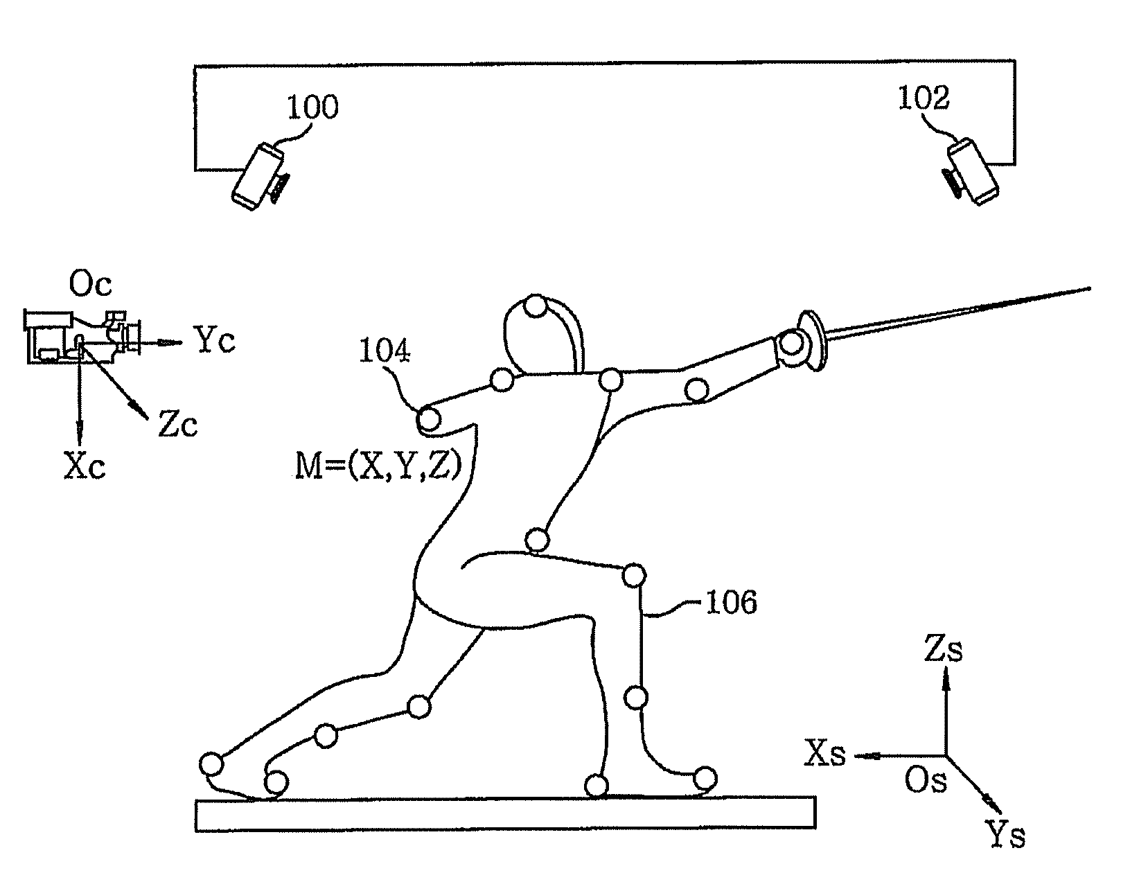
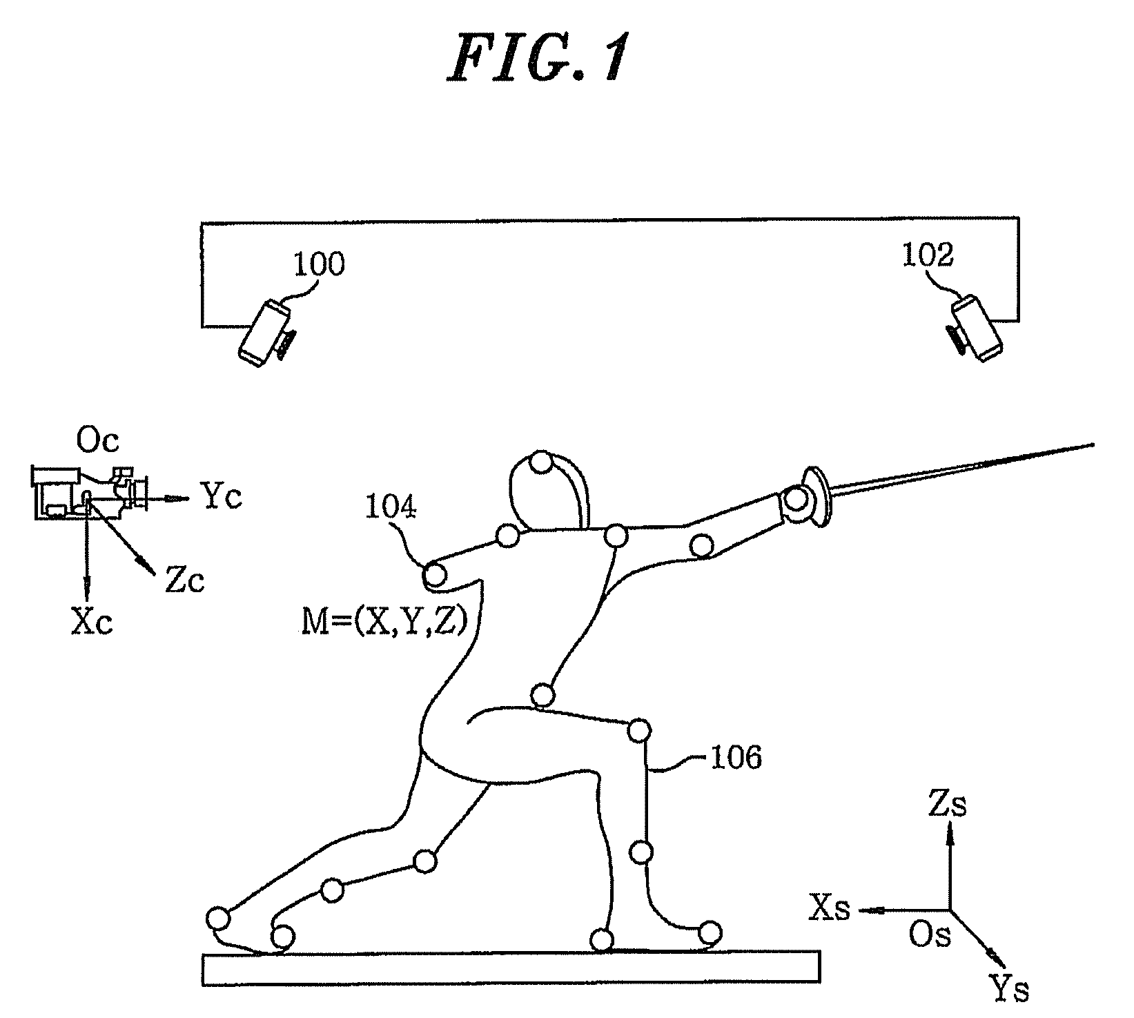
[0030]FIG. 1 illustrates the concept of image calibration using a dynamic marker attached to a target object taken by a motion capture camera and a high-resolution video camera in an optical motion capture system in accordance with an embodiment of the present invention

[0031]As shown in FIG. 1, in an optical motion capture system, a motion capture camera 102 and a high-resolution video camera 100 are connecte...


PUM


Abstract

An apparatus for calibrating images between cameras, includes: a detector for detecting dynamic markers from images taken by a motion capture camera and a video camera; a 3D position recovery unit for recovering 3D position data of the dynamic markers obtained by the motion capture camera; a 2D position tracking unit for tracking 2D position data of the dynamic markers obtained by the video camera; a matching unit for matching the 3D position data and the 2D position data of the dynamic markers; and a calibrating unit for converting the 3D position of the dynamic markers on a spatial coordinate system into image coordinates on an image coordinate system of the video camera to calculate intrinsic parameters and extrinsic parameters of the video camera to minimize a difference between coordinates of the 2D position data and the image coordinates.

Description

CROSS-REFERENCE(S) TO RELATED APPLICATION(S)[0001]The present invention claims priority of Korean Patent Application No. 10-2009-0026454, filed on Mar. 27, 2009, which is incorporated herein by reference.FIELD OF THE INVENTION[0002]The present invention relates to an apparatus and method for calibrating a motion capture camera and a high-resolution video camera in an optical motion capture system, and, more specifically, to an apparatus and method for calibrating images between cameras using a dynamic marker without using any separate camera calibrating apparatus or without attaching a calibrating marker to cameras.BACKGROUND OF THE INVENTION[0003]In the field of 3D contents production, calibration techniques between a motion capture camera and a high-resolution video camera are absolutely essential techniques for producing high-resolution 3D contents for use in more vivid and realistic HD broadcasts and movies, by precisely composing computer graphic animation based on 3D motion ca...

Claims


Application Information

Patent Timeline
Patent Type & Authority Patents(United States)
IPC IPC(8): H04N7/18
CPCG06T7/0018H04N5/2224H04N5/222G06T7/80G06T7/20H04N13/00
Inventor KIM, JONG SUNGKIM, HYE-MIKIM, JAE-HEAN
Owner ELECTRONICS & TELECOMM RES INST
Why Eureka
Try Eureka