Headset with a 360 degrees rotatable microphone boom and function selector

a headset and microphone technology, applied in the field of headsets for voice communication, can solve the problems of headset malfunction, failure of mechanical stop, and cumbersome headset user to change the microphone position, so as to reduce production costs, simplify the assembly of the headset, and reduce the effect of production cos

Active Publication Date: 2013-03-26
GN NETCOM
View PDF10 Cites 5 Cited by
  • Summary
  • Abstract
  • Description
  • Claims
  • Application Information

AI Technical Summary

Benefits of technology

[0005]According to a first aspect of the disclosure, the headset for voice communication comprises a housing and a pickup unit rotatably connected to the housing via a joint. The pickup unit comprises at least a first microphone, which is electrically connected via at least a first electric connection to an electronic circuit for processing signals from the first microphone. The electronic circuit is arranged in the housing. The first electric connection comprises a first sliding contact, which comprises a housing side and a microphone side. The two sides are mutually rotatable about a rotational axis. One of the housing side or the microphone side of the sliding contact comprises a first annular ring arranged so that the ring is positioned around the rotational axis. The other of the housing side or the microphone side comprises a number of contact members arranged in a radial distance from the rotational axis so as to provide an electrical connection between the first annular ring and the contact members. Providing a sliding electrical connection between the headset housing and the pickup unit eliminates the need for running wires for connection of the microphone to the electronic circuit through the joint. According to the objective of the disclosure, this overcomes the problems with such wires, by achieving a headset that improves user ergonomics, while maintaining a good sound quality of the audio signal transmitted from the microphone to the electrical circuit. Particularly, it eliminates the need for introducing a rotation stop in the joint to prevent wires from becoming twisted. Therefore, the resulting joint may be rotated 360 degrees, or even complete multiple rotations. As known in the art, the headset may comprise a secondary housing which comprises a second loudspeaker. In this case, the housing and the secondary housing may be connected by a headband, a neckband, or other suitable means of connection. The annular ring, of course, needs to be made of an electrically conductive material.
[0025]In another embodiment, the annular ring is formed in segments and comprises a number of isolated segments, the isolated segments being electrically isolated from a remainder of the segmented annular ring, the number of isolated segments corresponding to the number of contact members, wherein the isolated segments are arranged to communicate with the contact members when the sliding contact is in a special position. In this way, the sliding contact is adapted to enable a special function, such as a muting function, when the contact is in the special position. For contacts comprising a second or any additional annular rings, such annular rings may of course also be formed in segments and comprise isolated segments. Advantageously, the sliding contact should be adapted to disconnect both connections to the microphone, in order to prevent noise from being picked up by the circuit.

Problems solved by technology

However, failure of the mechanical stop is a common cause for malfunction of headsets, as such stops may simply break off.
Furthermore, the mechanical stop makes it more cumbersome for a headset user to change the microphone position, e.g. when switching from one ear to the other.
However, this solution is space consuming and difficult to integrate with an electronic circuit in the headset housing.
Furthermore, the solution is detrimental to the audio quality of the signal transmitted over the sliding contact.
If only one contact member is used per connection, variations in resistance will lead to introduction of noise in the audio signal transmitted over the connection.
Changes, e.g. oxidization, in the surfaces of the first annular ring and / or the contact members where they may come in contact have detrimental effects on the sound quality of the audio signal transmitted over the connection, since such changes may cause variations in the resistance of the connection, as the joint is rotated.

Method used


Image

  • Headset with a 360 degrees rotatable microphone boom and function selector
  • Headset with a 360 degrees rotatable microphone boom and function selector
  • Headset with a 360 degrees rotatable microphone boom and function selector

Examples


Embodiment Construction

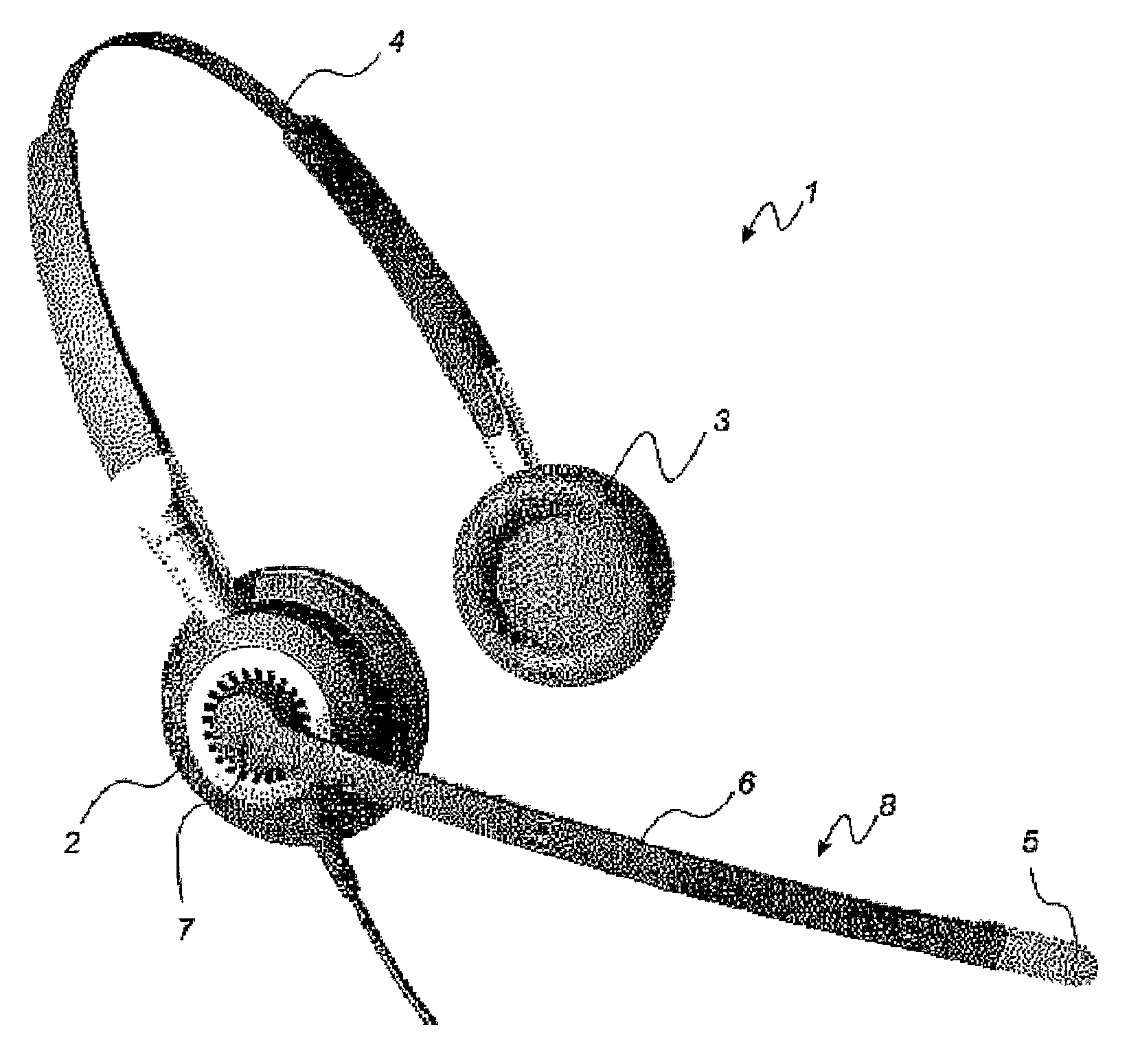
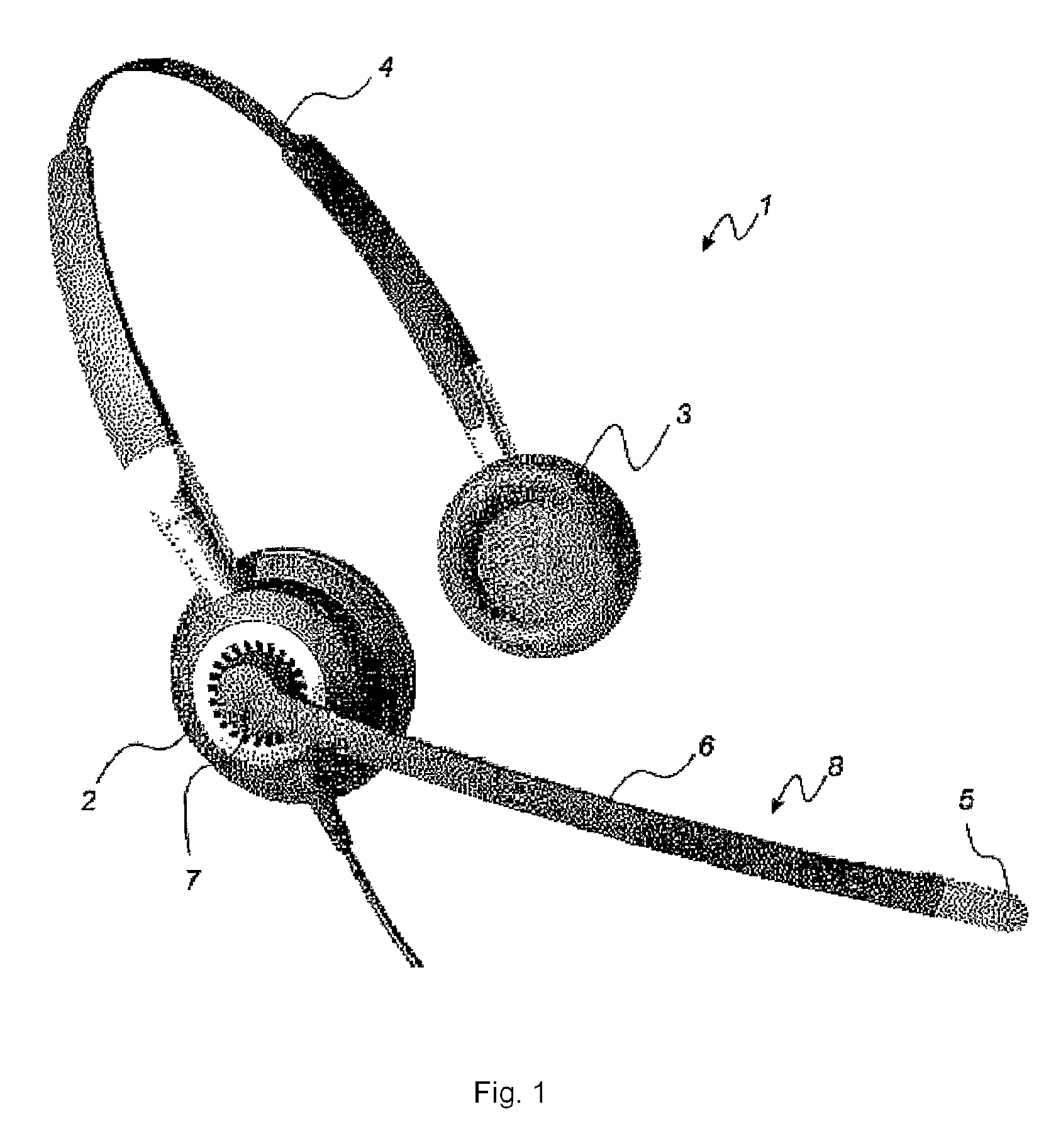
[0060]A headset 1 for voice communication is illustrated in FIG. 1. The headset 1 comprises an earphone housing 2 and, optionally, a second earphone housing 3 including an earphone (one or both ears), which are interconnected and held in place on the head of a user by a head band 4. A microphone 5 is mounted on a pickup unit in form of a microphone boom 6, which is rotatably connected to the earphone housing 2 via joint 7.

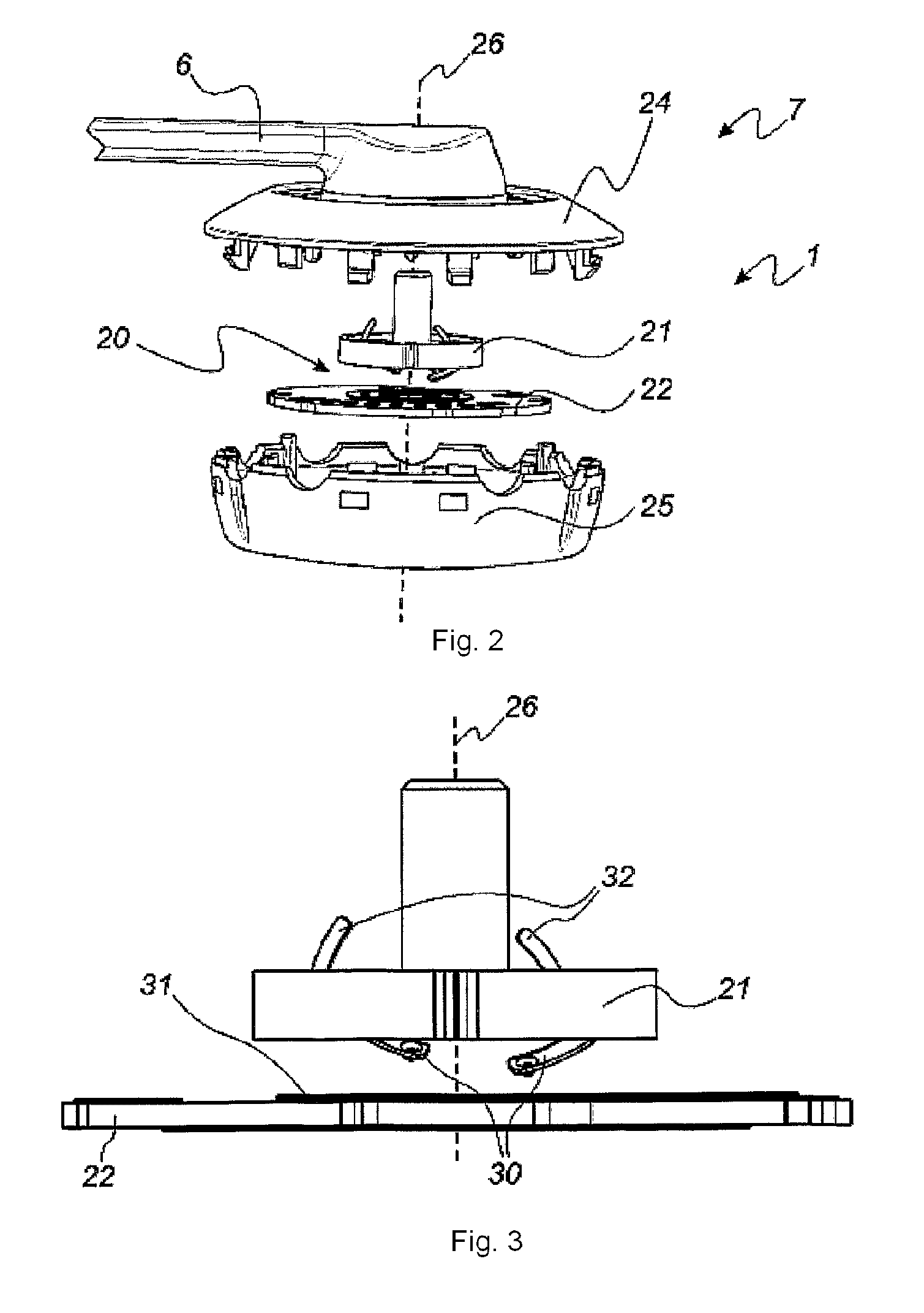
[0061]An exploded view of the housing 2 comprising a rotatable joint 7 is illustrated in FIG. 2. As can be seen, the rotatable joint comprises a sliding contact 20. The sliding contact 20 comprises a contact wheel 21 on a microphone side and a printed circuit board 22 (PCB) on a housing side of the sliding contact between the two housing covers 24, 25. The microphone boom 6 and the housing are mutually rotatable about a rotational axis 26 indicated with a dashed line in the figure. In one embodiment, the PCB 22 further comprises most of the components of the electr...


PUM


Abstract

A headset and method for voice communication comprising a housing (2) and a pickup unit (8) rotatably connected to the housing via a joint (7). The pickup unit (8) transmits its position to circuitry which in turn enables functions according to its position. When the unit is moved to a predetermined position and a function is enabled, the user is preferably notified by an audible signal in the earphone. The unit may be rotated, pivoted or twisted and even ratcheted to various positions to engage different functions, such as mute, volume up / down, activate Bluetooth® link etc. One position detection includes a sliding contact (20, 70) mutually rotatable about a rotational axis (26) and a annular ring (50) arranged so that the ring (50) is positioned around the rotational axis (26) so as to provide an electrical connection between the first annular ring (50) and the contact members (30).

Description

TECHNICAL FIELD[0001]The present disclosure relates to a headset for voice communication comprising a housing and a pickup unit rotatably connected to the housing via a joint and a position sensor coupled to at least one function.BACKGROUND ART[0002]It is well known to provide a headset for voice communication with a microphone on a microphone boom that is rotatably mounted to the remaining parts of the headset via a joint. To establish an electrical connection to the microphone from the electrical circuit in the headset, a set of wires are commonly run through the joint. In order to protect these wires from damage due to twisting, arising from rotation of the joint, a mechanical stop is typically included to restrict rotation. Such a mechanical stop then acts to limit the travel of the joint to less than a full revolution or to less than 360 degrees. However, failure of the mechanical stop is a common cause for malfunction of headsets, as such stops may simply break off. Furthermor...

Claims


Application Information

Patent Timeline
Patent Type & Authority Patents(United States)
IPC IPC(8): H04M1/00H04M9/00H04R25/00
CPCH04M1/05H04R1/1041H04M1/6058H04R1/08
Inventor BIRCH, OLE
Owner GN NETCOM
Why Eureka
Try Eureka