Goal detector for detection of an object passing a goal plane

a technology for object detection and goal plane, which is applied in the direction of target detectors, sports equipment, weapons, etc., can solve the problems of high update rate, difficult to determine correctly, and insufficient spatial and temporal resolution of video cameras to provide the necessary information. , to achieve the effect of improving precision

Active Publication Date: 2013-04-02
FRAUNHOFER GESELLSCHAFT ZUR FOERDERUNG DER ANGEWANDTEN FORSCHUNG EV
View PDF29 Cites 14 Cited by
  • Summary
  • Abstract
  • Description
  • Claims
  • Application Information

AI Technical Summary

Benefits of technology

[0009]The invention provides a system for detecting the passage of an object passing a goal plane with an improved precision.

Problems solved by technology

However, this may be very difficult to determine correctly in situations where the ball is returned quickly and has only just passed, or not passed, the goal plane, and it is particularly difficult if the referee is positioned unsuitably with respect to the goal plane or is engaged in other activity of the match.
Video camera may also be used to monitor the goal planes, but the spatial and temporal resolution of video-cameras are often not sufficient to provide the necessary information in cases of doubt.
However, the determination of the passage of the goal plane is a very delicate matter, both because it may be decisive for the outcome of the sports match and because the distances are small and the velocity of the object often very high, so that a position determining system to provide a reliable determination of whether the object has passed the goal plane must be very precise in the determination of the position and at the same time have a very high update rate of the position determination.
Position systems with a sufficiently precise determination of the position of a sports object and a sufficiently high update rate to provide reliable indications of the crossing of a goal plane, are very expensive to install and maintain.
A reflector of 30 inch width, 76 cm, will provide a detection zone of 4 inch width, 10 cm, which together with other uncertainties of the system is acceptable for use with American football as the patent is directed at, but is unacceptable for many other sports games and a much larger reflector would be required.
However, this arrangement has the drawback that the spatial resolution is limited by the size of the ball as the coil of the sensor substantially encircles the ball diameter, which is of increasing importance with decreasing distance between the ball and the detection coil.
This is not a major problem when detecting most scored goals when the ball clearly passes the goal plane, but in situations of doubt where the ball only just passes or do not pass the goal plane completely and the ball is close to the coils, the spatial resolution is not sufficient to decide with a satisfactory precision whether or not the goal has been scored.

Method used


Image

  • Goal detector for detection of an object passing a goal plane
  • Goal detector for detection of an object passing a goal plane
  • Goal detector for detection of an object passing a goal plane

Examples


Embodiment Construction

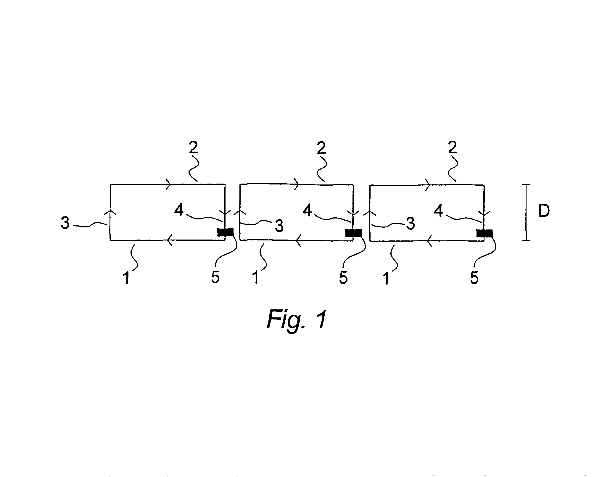
[0056]In FIG. 1, three sections of the cross bar of a football goal are shown schematically as seen from above. Each section comprises a conductor 1 in a first plane and a parallel conductor 2 in a second plane and two intermediate conductors 3, 4 connecting the other conductors 1, 2 to form a circuit wherein a current may run as indicated by the arrowheads. Each section has a separate control unit 5 for feeding current into the circuit of the section and possibly obtain data relating to objects in which a power is inducted by the section. The distance D between the parallel conductors 1, 2 in the horizontal direction normal to the goal plane is preferably chosen to be about the diameter of a standard football according to the regulations set by FIFA, more generally speaking from 15 to 50 centimetres. In a specific embodiment, the parallel conductors 1, 2 in the same plane of adjacent sections may be electrically connected, so that the front conductor 1 of one section is connected t...


PUM


Abstract

A system is disclosed for detection of whether a movable object, such as a sports object, e.g. a football or an ice hockey puck, has passed goal plane. It is known to encircle the goal plane with conductors to produce an electromagnetic field to excite signal emitter means in the movable object, alternatively detect the signal emitted by the emitter means. With the present invention these circuits are sectioned into a plurality of separate circuits, which provides an improved spatial resolution of the system in particularly when the movable object is close to the conductors.

Description

TECHNICAL FIELD OF THE INVENTION[0001]The present invention relates to a system for detection of whether a movable object, such as a sports object, e.g. a football or an ice hockey puck, has passed a flat plane in space, such as a goal plane defined e.g. as a vertical plane extending from a goal line or a horizontal plane defined by the upper rim of the basketball basket.BRIEF DESCRIPTION OF THE RELATED ART[0002]Traditionally, the referee or referees of a sports match decides from visual observation whether or not the ball has passed the goal plane. However, this may be very difficult to determine correctly in situations where the ball is returned quickly and has only just passed, or not passed, the goal plane, and it is particularly difficult if the referee is positioned unsuitably with respect to the goal plane or is engaged in other activity of the match. Video camera may also be used to monitor the goal planes, but the spatial and temporal resolution of video-cameras are often n...

Claims


Application Information

Patent Timeline
Patent Type & Authority Patents(United States)
IPC IPC(8): F41J5/00
CPCA63B63/004A63B43/004A63B71/0605A63B43/00A63B63/00A63B2024/0043A63B2220/89A63B2225/50A63B71/06
Inventor ESKILDSEN, JORN
Owner FRAUNHOFER GESELLSCHAFT ZUR FOERDERUNG DER ANGEWANDTEN FORSCHUNG EV
Why Eureka
Try Eureka