Cutting insert and cutting tool

a cutting tool and insert technology, applied in the field of cutting tools, can solve the problems of tight clamping inserts that pivot ever so slightly about that point, adversely affect the precision to which the workpiece can be machined, and damage to workpieces, so as to minimize reduce the tendency of inserts, and minimize the effect of inserts

Inactive Publication Date: 2013-04-02
PRAMET TOOLS
View PDF17 Cites 5 Cited by
  • Summary
  • Abstract
  • Description
  • Claims
  • Application Information

AI Technical Summary

Benefits of technology

[0005]To minimize any tendency of the insert to move relative to a toolholder during use, an insert abutment surface of the insert-receiving pocket of the toolholder might be provided with a recess so that contact between two points of the insert abutment surface and the insert's insert supporting surface can be ensured. By providing a recess in the insert abutment surface or the insert supporting surface, even if an insert supporting surface or an insert abutment surface is less than perfectly flat, there will be two points of contact between the two surfaces, which reduces a tendency of the insert to rock relative to the toolholder.
[0006]Typically, inserts have holes for receiving a clamping scr

Problems solved by technology

Application of high forces to the insert, such as during a machining operation, can cause even a very tightly clamped insert to pivot ever so slightly about that point, line, or area of contact.
Suc

Method used


Image

  • Cutting insert and cutting tool
  • Cutting insert and cutting tool
  • Cutting insert and cutting tool

Examples


Embodiment Construction

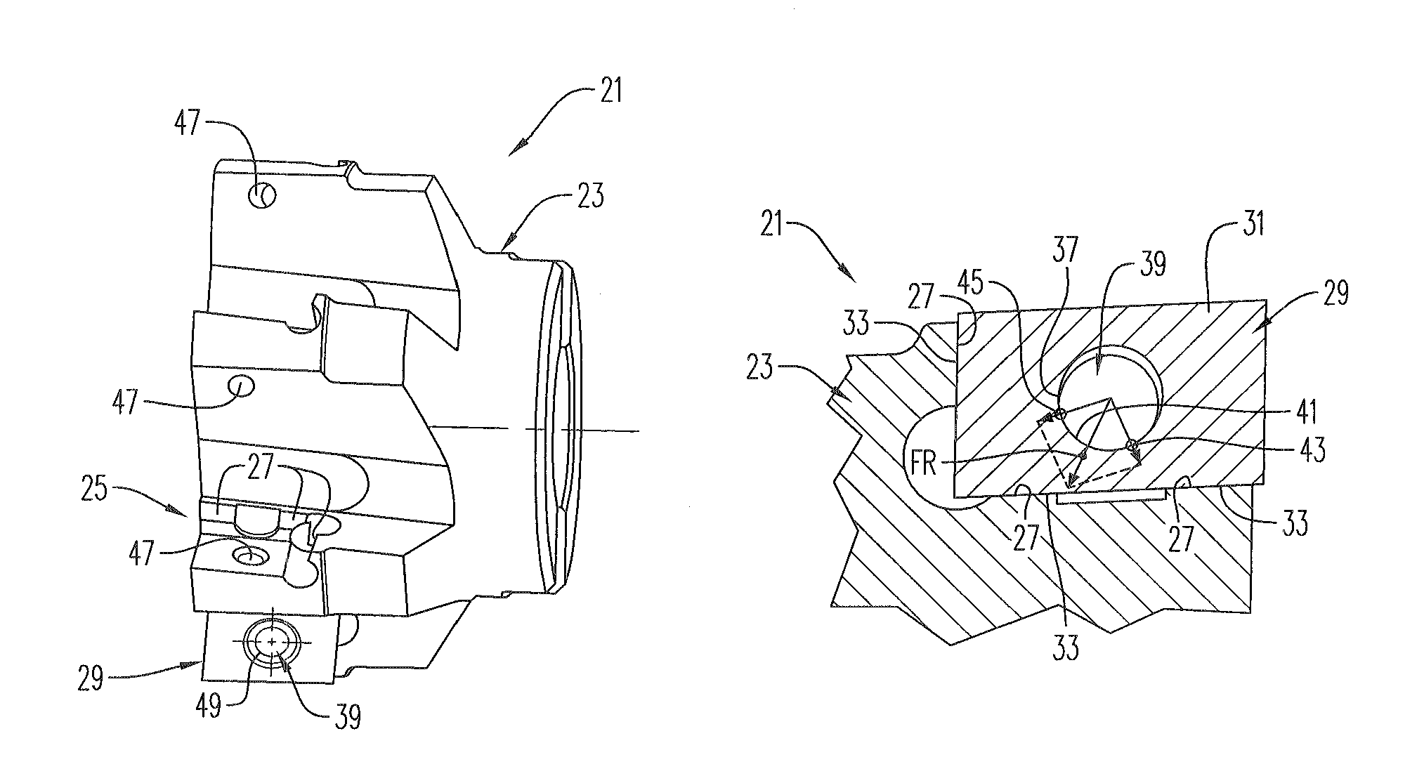
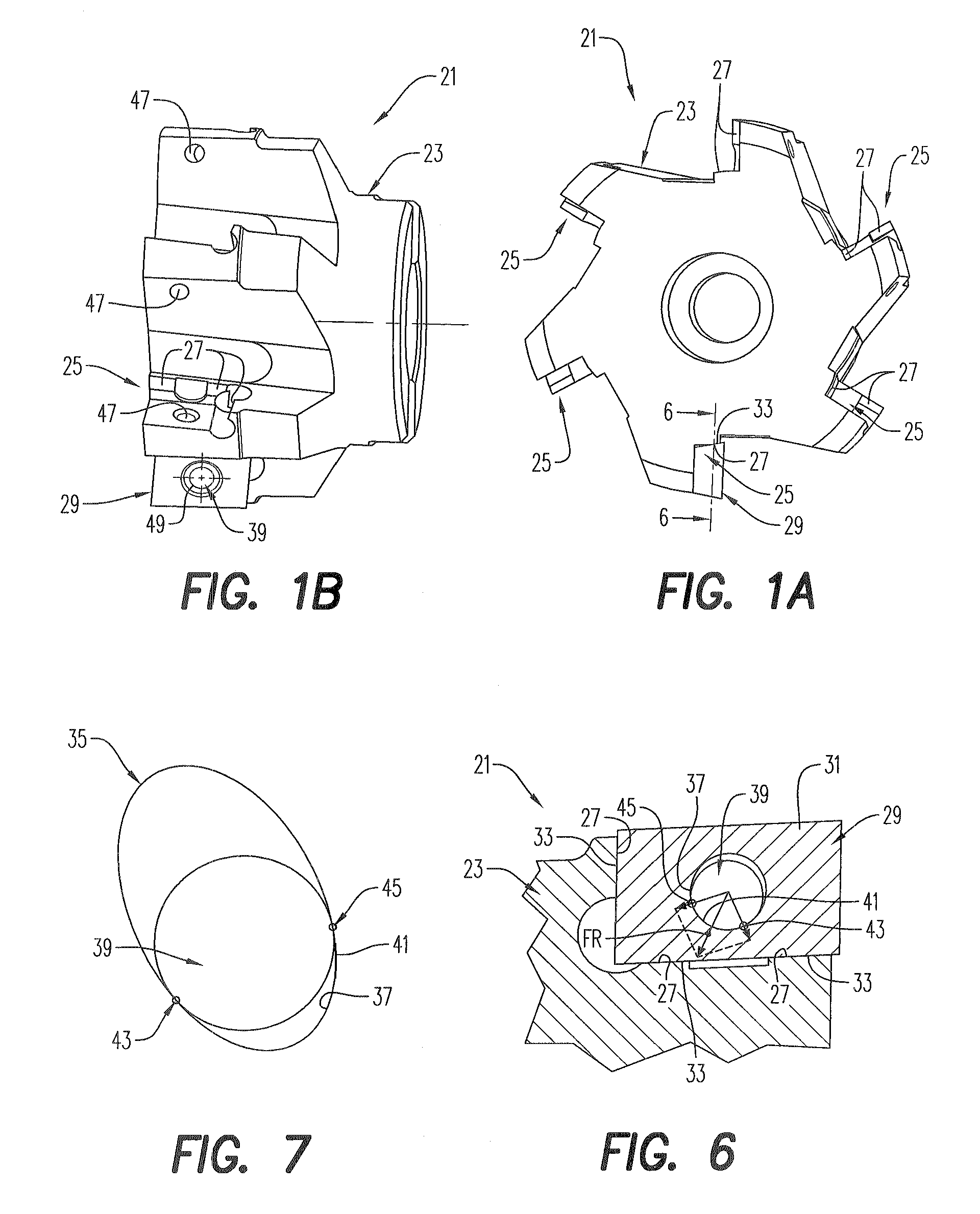
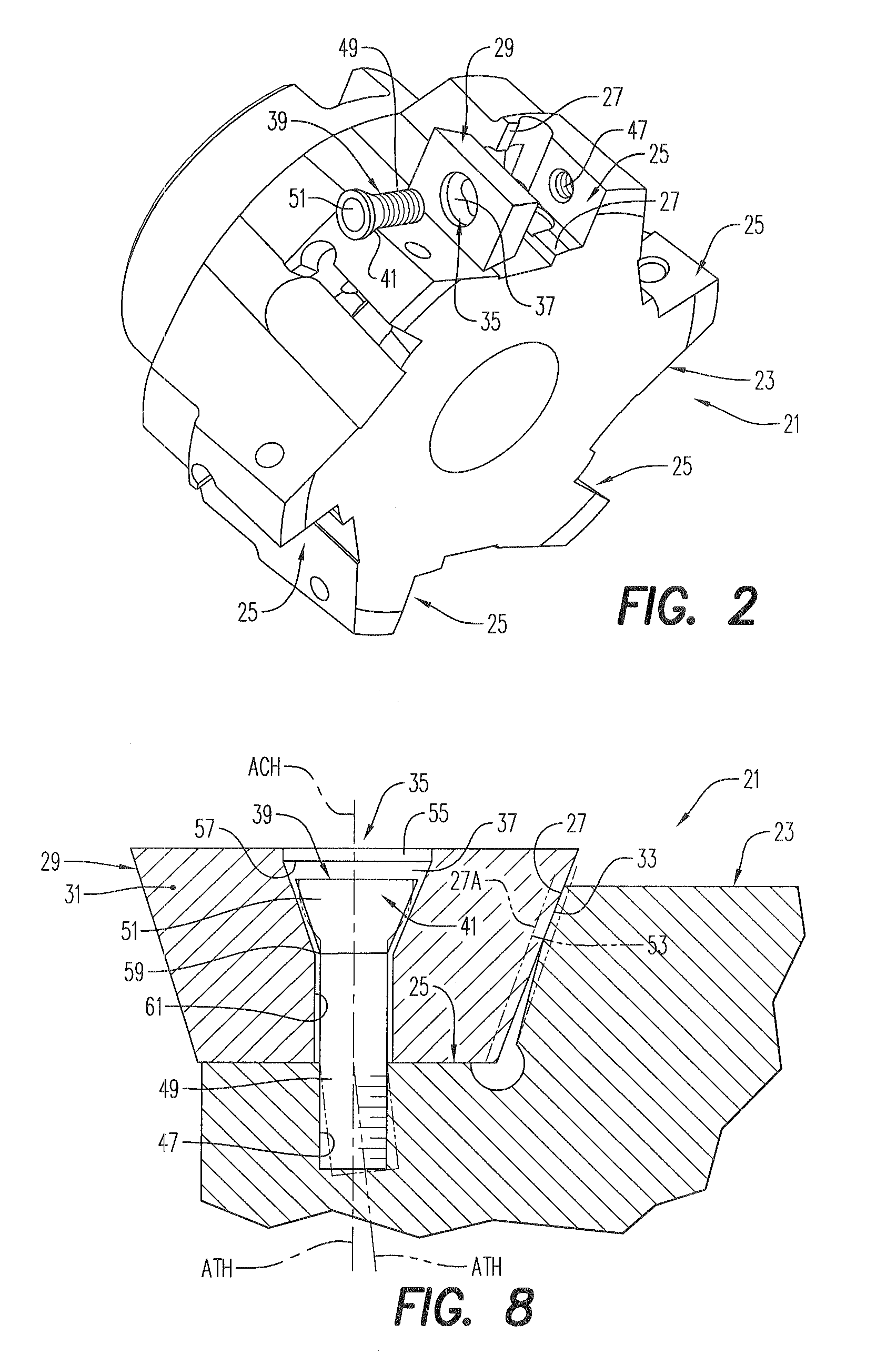
[0018]A cutting tool 21 according to an embodiment of the present invention is shown in FIGS. 1A-1B, 2, 6, and 8. The illustrated cutting tool 21 is a milling tool, however, aspects of the present invention are considered to have application to all types of cutting tools that include replaceable cutting inserts, including milling, drilling, boring, and turning tools. The cutting tool 21 comprises a toolholder 23 comprising at least one insert-receiving pocket 25 that includes at least one side abutment surface 27. Often, cutting tools 21 such as the illustrated milling tool will include a plurality of insert-receiving pockets 25.

[0019]The cutting tool 21 also includes a cutting insert 29 receivable in an insert-receiving pocket 25. As seen in FIGS. 3A-3E and 4, the cutting insert 29 comprises an insert body 31 having at least one insert supporting surface 33 (FIGS. 1A and 8) and a clamping hole 35 including a clamping surface 37 defining at least part of a non-circular, substantiall...


PUM

PropertyMeasurementUnit
Forceaaaaaaaaaa
Angleaaaaaaaaaa
Shapeaaaaaaaaaa

Abstract

The present invention relates to cutting tools and, more particularly, to cutting tools using clampable cutting inserts. The cutting tool includes a toolholder including at least one insert-receiving pocket, the insert-receiving pocket including at least one side abutment surface. The cutting tool further includes a cutting insert comprising an insert body having at least one insert supporting surface and a clamping hole including a clamping surface defining at least part of a non-circular, substantially elliptical cone. The cutting tool further includes a clamp having a clamp surface adapted to contact the clamping surface at two contact points such that the at least one side abutment surface and the at least one insert supporting surface are secured in a contacting relationship.

Description

BACKGROUND AND SUMMARY[0001]The present invention relates to cutting tools and, more particularly, to cutting tools using clampable cutting inserts.[0002]In various forms of cutting tools, such as rotating tools and turning tools, it is known to clamp replaceable cutting inserts in pockets on toolholders. Using replaceable, clampable cutting inserts instead of, e.g., cutting inserts that are brazed to a toolholder facilitates replacement of the inserts when worn. Often, the cutting inserts are indexable to a plurality of positions to replace worn portions of a cutting edge of the insert with a sharp portion. A variety of techniques for clamping the replaceable inserts to the toolholder are known, and include pin arrangements, screw or bolt arrangements, and clamping arm arrangements.[0003]Whatever clamping arrangement is used to clamp the insert relative to the toolholder, it is highly desirable that the insert be securely clamped and that any capacity of the insert to move during u...

Claims


Application Information

Patent Timeline
IPC IPC(8): B23C5/02
CPCB23C5/2221B23C2200/361B23C2265/16Y10T407/2276Y10T407/23Y10T407/2288Y10T407/235B23C5/2213B23B27/16B23B51/00B23C5/2204
Inventor RYSAVY, JAROMIR
Owner PRAMET TOOLS
Why Eureka
Try Eureka