Compact multi frequency-range impedance tuner

a multi-frequency-range, compact technology, applied in the direction of multiple-port network, waveguide-type devices, electrical equipment, etc., can solve the problems of inconvenient use, limited frequency bandwidth of electro-mechanical impedance tuners, and limited frequency bandwidth of their natur

Inactive Publication Date: 2013-04-02
TSIRONIS CHRISTOS
View PDF6 Cites 20 Cited by
  • Summary
  • Abstract
  • Description
  • Claims
  • Application Information

AI Technical Summary

Problems solved by technology

Electro-mechanical impedance tuners are, by their nature, limited in frequency bandwidth.
It is obvious that at frequencies below a few hundred megahertz the size of a slide screw tuner is prohibitive.
Because the angle between vectors is fixed the bandwidth of said tuner is limited and the maximum reflection created is not fully flat over the whole frequency range.

Method used


Image

  • Compact multi frequency-range impedance tuner
  • Compact multi frequency-range impedance tuner
  • Compact multi frequency-range impedance tuner

Examples


Embodiment Construction

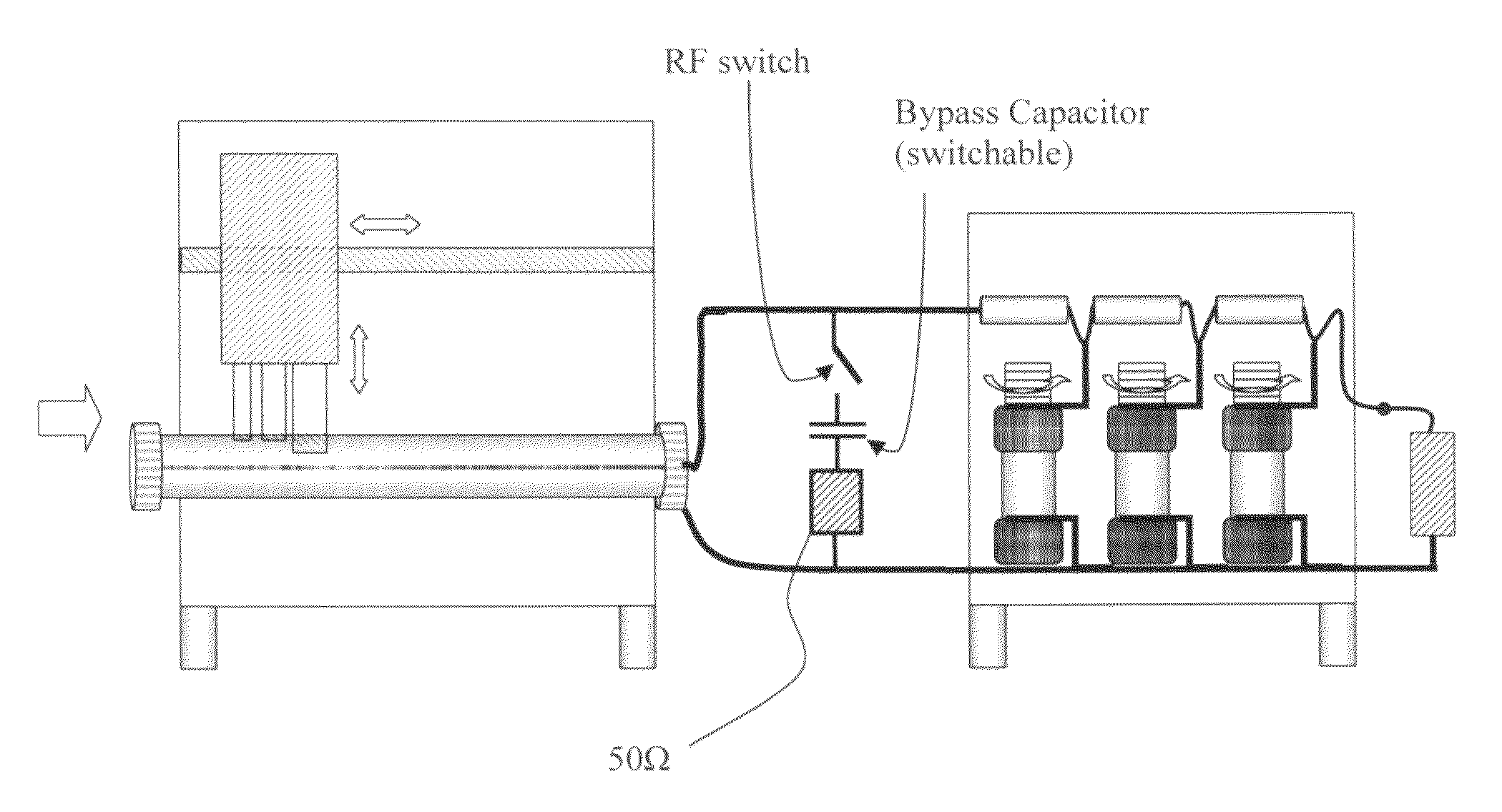
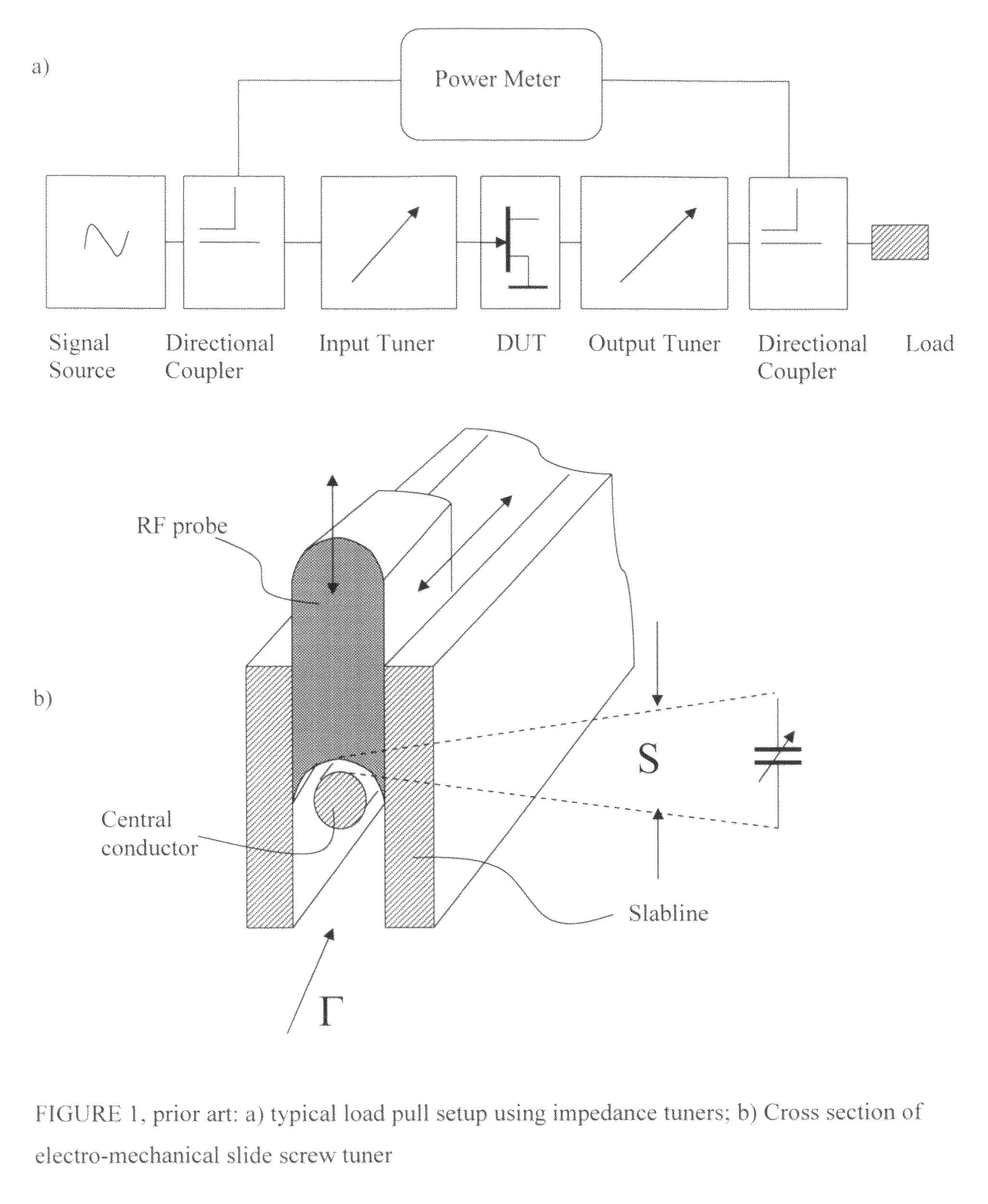
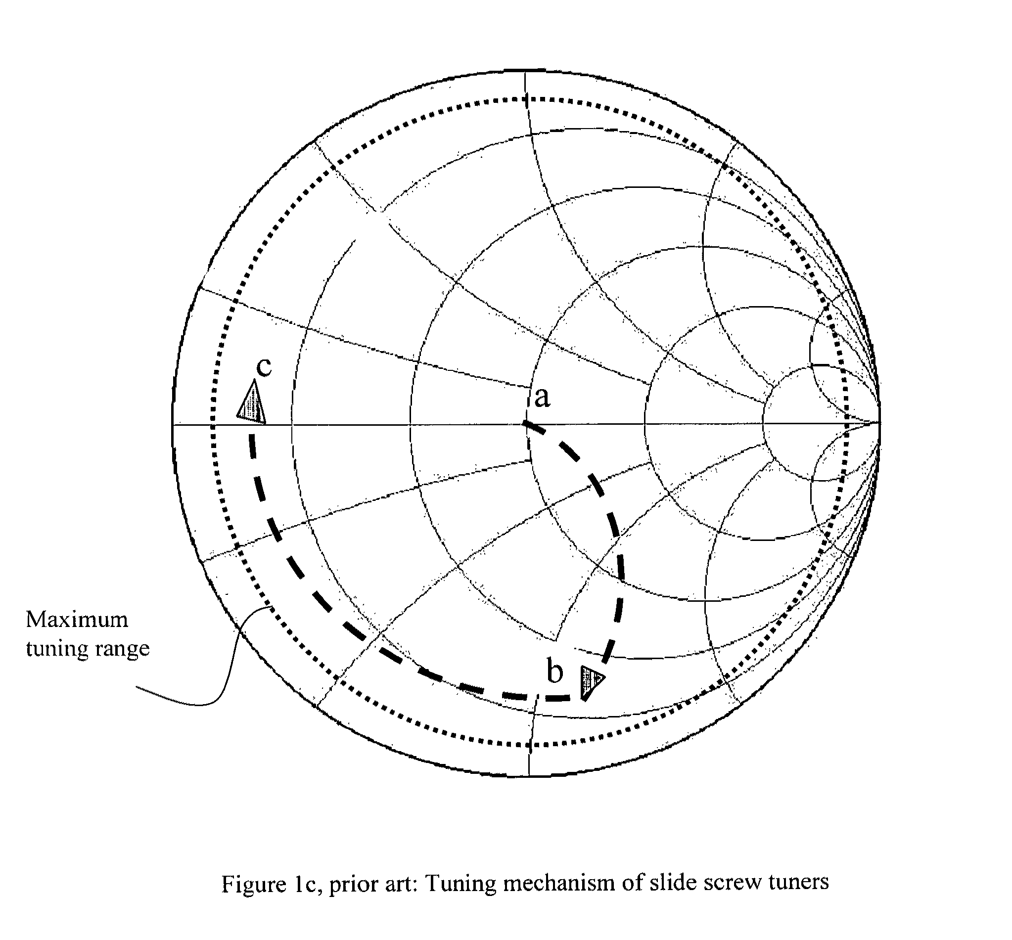
[0051]This invention describes a microwave impedance tuner apparatus which covers instantaneously a very large frequency bandwidth of up to 10 or 16 octaves or up to 3.6 decades (10 or 50 MHz to 6, 18, 40 or 50 GHz). Such an endeavor has never been considered before. In fact it is possible, when appropriate technologies are used and are combined with associated tuning algorithms, which allow the tuners in cascade to compensate for each-other's residual reflections. In order to understand this operation we need to review the residual reflections of the low frequency tuners at high frequencies (FIGS. 7, 12). Also in order to avoid intrinsic reflections due to the coaxial RF connectors, which have upper frequency limits (cut-off frequencies) all tuners in the cascade must be equipped with connectors which allow signal flow at the highest frequency; for instance, if the highest frequency is 6 GHz we can use either 7 / 16, N or APC7 (7 mm) coaxial connectors. For 18 GHz we must use either ...


PUM


Abstract

An automatic multi frequency-range electro-mechanical impedance tuner covers frequencies from a low megahertz to a high gigahertz range, by combining a high frequency with one or two a low frequency tuner modules; the low frequency module is made using either variable phase shifter-capacitor or multi-capacitor-transmission line tuner structures. The high frequency module is a single, double or triple probe slide screw tuner covering up to 1.5 decades in frequency; the low frequency tuner is using cascades of three or more capacitor-coax cable tuning sections or a low frequency phase shifter combined with a variable shunt capacitor; the low frequency tuner can operate as low as a few megahertz whereas the high frequency tuner can operate up to several gigahertz. Depending on the application, low frequency parallel-blade capacitors or high frequency coaxial trimmers are used. Typical cross-over frequencies between low and high frequency modules range from 200 to 800 megahertz, lowest frequencies can reach below 10 megahertz and highest frequencies 26 to 40 gigahertz. Appropriate calibration, control and tuning procedures allow for a fully integrated operation.

Description

PRIORITY CLAIM[0001]Not ApplicableCROSS-REFERENCE TO RELATED ARTICLES[0002][1]“Product Note #41: Computer Controlled Microwave Tuner, CCMT”, Focus Microwaves Inc., January 1998.[0003][2] Tsironis, C. U.S. Pat. No. 6,674,293, “Adaptable Pre-matched tuner system and method”.[0004][3] Catalogue: Sprague AIRTRIM 1-16 pF resonance up to 5 GHz[0005][4] Computer Design of Microwave Circuits, K. C. Gupta et al, Artech House, 1981, App. 2.1 case 7.[0006][5] Tsironis, C. U.S. Pat. No. 7,135,941, Triple probe automatic slide screw load pull tuner and method.[0007][6] Tsironis, C. U.S. Pat. No. 7,646,267, “Low frequency electro-mechanical impedance tuner”.[0008][7] Ocean State Electronics, Variable Capacitor Datasheet[0009][8] Tsironis, C. U.S. patent application Ser. No. 12 / 654,463, “Wideband low frequency impedance tuner”.STATEMENT REGARDING FEDERALLY SPONSORED RESEARCH OR DEVELOPMENT[0010]Not ApplicableREFERENCE TO SEQUENCE LISTING, A TABLE, OR A COMPUTER PROGRAM LISTING COMPACT DISC APPENDI...

Claims


Application Information

Patent Timeline
Patent Type & Authority Patents(United States)
IPC IPC(8): H03H7/38
CPCH01P5/04H03H7/38H03H7/40
Inventor TSIRONIS, CHRISTOS
Owner TSIRONIS CHRISTOS
Why Eureka
Try Eureka