
Systems and methods for determining muscle force through dynamic gain optimization of a muscle PID controller

a dynamic gain optimization and muscle force technology, applied in the field of control schemes, can solve problems such as potential accuracy problems, fixed muscle force, and complex kinematic profiles, and achieve the effect of minimizing collective muscle effor

Active Publication Date: 2013-04-02
LIFEMODELER
View PDF5 Cites 25 Cited by
  • Summary
  • Abstract
  • Description
  • Claims
  • Application Information

AI Technical Summary

Benefits of technology

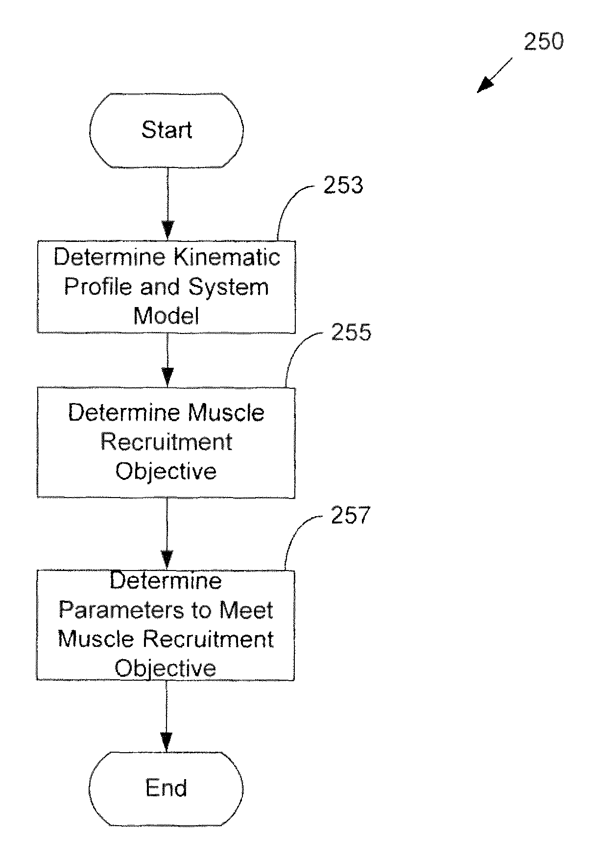
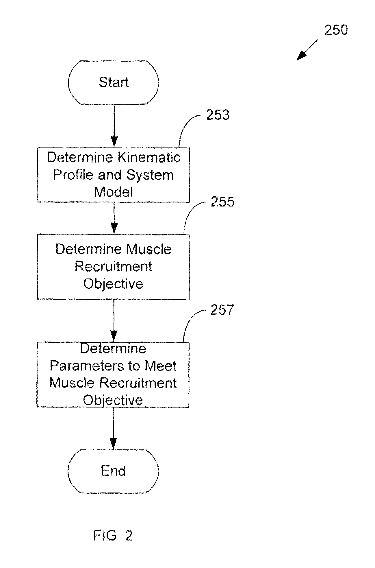
[0012]In another aspect, a computer readable medium storing instructions that, when executed by a computer, cause the computer to perform a method for simulating muscle forces is provided. The method includes determining a kinematic profile, determining a first muscle that contributes to the kinematic profile, determining a second muscle that contributes to the kinematic profile, and determining muscle forces for the first and second muscles that meet the kinematic profile and minimize collective muscle effort.
[0013]In another aspect, a method for designing a replacement join is presented. The method includes determining a kinematic profile associated with joint, determining a first muscle that contributes to the kinematic profile, determining a second muscle that contributes to the kinematic profile, determining muscle forces for the first and second muscles that meet the kinematic profile and minimize collective muscle effort; and modifying the replacement joint based, at least in part, on the muscle forces.

Problems solved by technology

However, kinematic profiles may also be more complex.
There are two major limitations to this approach.
First, it is based on sequential static solutions rather than a true dynamic solution.
This has potential accuracy problems due to the limitation that the muscle forces are fixed over the time period between static solutions, rather than being a truly dynamically varying muscle force as would be the case with real muscles.
The second limitation is related to solution formulation.
For situations where multiple muscle activations, or recruitment patterns, are able to meet the same kinematic profile, however, the approach does not preferentially choose the solution that has the minimum force, or any other assumed recruitment objective.

Method used


Image

  • Systems and methods for determining muscle force through dynamic gain optimization of a muscle PID controller
  • Systems and methods for determining muscle force through dynamic gain optimization of a muscle PID controller
  • Systems and methods for determining muscle force through dynamic gain optimization of a muscle PID controller

Examples


Embodiment Construction

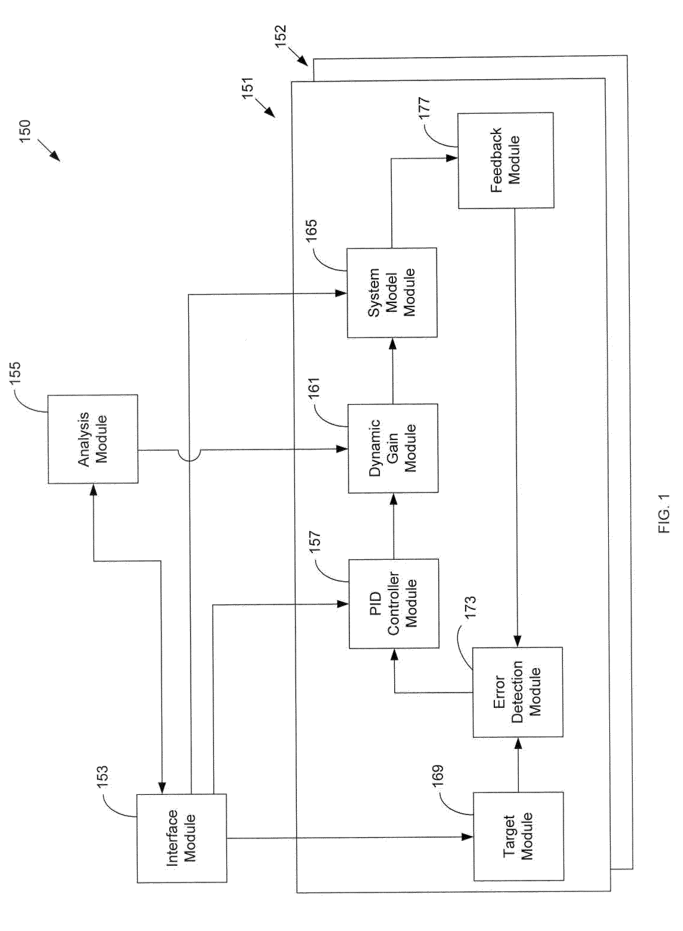
[0020]Embodiments of the current invention take advantage of the PID muscle force control (e.g., speed and accuracy of the solution kinematics and muscle physiological limits) and add a desired recruitment goal as defined by an optimization objective. A benefit associated with present embodiments is that the resultant solution remains a true dynamic solution using PID controllers, so the solution remains fast and accurate.

[0021]Embodiments of the current invention extend a PID-based muscle force algorithm to include a direct dynamic optimization of PID time-varying gains such that the resulting PID-based muscle force will directly generate muscle forces optimized to meet a user defined objective, while maintaining physiological force limits and kinematic profiles. The objective of the optimization may be to minimize the collective effort each of the muscles. The collective effort of the muscles may he represented by the sum squared muscle forces, the sum squared activation levels, m...


PUM


Abstract

Systems and methods for determining muscle force are presented. Proportional, integral, and derivative control is used to simulate muscle forces for multiple muscles contributing to a kinematic profile. The simulated muscle forces arc modified by dynamic gains that are calculated in order to achieve a muscle recruitment objective such as minimizing collective muscle effort while still achieving the kinematic motion.

Description

RELATED APPLICATION[0001]The present application claims the benefit of U.S. provisional patent application no. 61 / 236,006, filed Aug. 21, 2009, which is incorporated herein by reference in its entirety.BACKGROUND[0002]1. Field of the Invention[0003]The invention relates generally to control schemes. In one embodiment, a system for optimizing a proportional, integral, derivative (PID) controller through the use of dynamic gains is disclosed.[0004]2. Related Art[0005]One of the major objectives of a biomechanical simulation tool is to determine the physiologically relevant muscle forces required for a given muscular-skeletal model performing a prescribed kinematic profile. Examples of kinematic profiles include the flexion of elbow or knee. However, kinematic profiles may also be more complex. For example, a kinematic profile may include the motion of walking. For many models and kinematic profiles there are multiple muscle activations that are possible. The goal of the simulation the...

Claims


Application Information

Patent Timeline
Patent Type & Authority Patents(United States)
IPC IPC(8): G06F15/00G16H20/30G16Z99/00
CPCG06F19/3481G06F19/3437G16H50/50G16H20/30G16Z99/00
Inventor BERGEON, MILTON SCOTTJACKSON, DAVID BRIANMCGUAN, SHAWN PATRICK
Owner LIFEMODELER
Learn More