Operating device having force feedback

a technology of operating device and force feedback, which is applied in the direction of mechanical equipment, rotary machine parts, transportation and packaging, etc., can solve the problems of operator not being able to receive the haptic sensation, driver is unable to easily recognize, and no longer a mechanical coupling between the operating lever and the operating lever, so as to reduce the size of the actuator and reduce the energy consumption of the actuator

Inactive Publication Date: 2013-04-09
ZF FRIEDRICHSHAFEN AG
View PDF25 Cites 11 Cited by
  • Summary
  • Abstract
  • Description
  • Claims
  • Application Information

AI Technical Summary

Benefits of technology

[0022]Is this way, the counterforce element in form of a controllable damper device otherwise required as a separate component in conventional devices can be eliminated, and the function of the counterforce element can be integrated into the joint of, for example, an operating lever, saving considerable installation space. The costs, complexity of the structure and required installation space for an operating device with force-feedback can hence be significantly reduced with the invention.
[0041]The force generation with the counterforce element can also be supported by the motor-driven actuator. In this situation, the actuator is responsible for automatic movements of the operating element (for example for a realistic return of the selection lever to its locking position) and also for supporting the generation of a counterforce, for example for the haptic simulation of a locking mechanism, or in the event that actually impermissible selection lever positions must be blocked.

Problems solved by technology

However, with electrical or shift-by-wire operation of gear-changing transmissions, there is no longer a mechanical coupling between the operating lever in the passenger compartment and then automobile transmission in the engine compartment.
Due to the absence of a mechanical linkage between the transmission actuators and the operating lever, the position of the transmission, any gear shift locks or impermissible shifting commands can no longer provide direct feedback about the position of the operating lever so that it can be sensed by the operator.
For example, with shift-by-wire-controlled transmissions, the driver is unable to easily recognize based on certain shifting positions which are perceptibly blocked on the operating lever that shift lever positions, gear positions and / or shifting commands may not be allowed under the current driving conditions and should therefore also not be selected.
Likewise, with a shift-by-wire actuation, the actual execution of the operator's shifting commands by the transmission is also not fed back to the operating lever, so that the operator is unable to receive the haptic sensation when the shifting operation is executed, in the same way he is used to, for example, from mechanically operated gearboxes with their locking mechanism and gear synchronizing locks.
However, this operating device known from the state-of-the-art with an electronically controllable motion damper has disadvantages because the motion damper according to the teaching of this document must be incorporated as an additional assembly in the region of the operating lever or in the housing of the operating device.
This increases the complexity of the structure and requires a separate installation space which is frequently not available with the increasingly smaller operating devices for modern automobile transmissions.
In addition, according to the teaching in this document, generation of the restoring force in this document also requires an actuator drive, resulting in not insignificant energy consumption and requiring additional space.

Method used


Image

  • Operating device having force feedback
  • Operating device having force feedback
  • Operating device having force feedback

Examples


Embodiment Construction

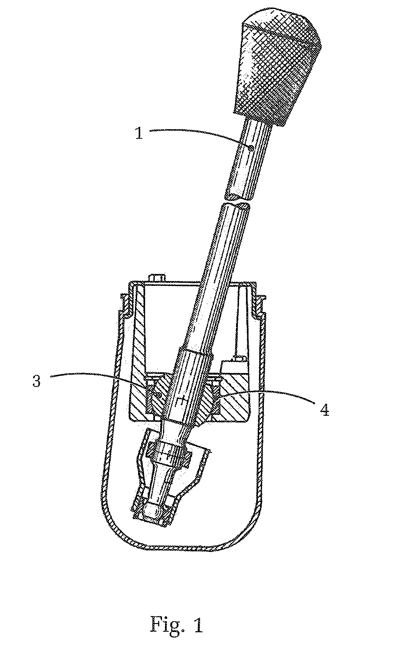
[0047]FIG. 1 shows first a conventional operating lever 1 with a ball joint according to the state-of-the-art. As is clearly evident, the operating lever 1 includes a ball joint with a ball 3 and a ball socket 4. The operating lever 1 can hence be initially pivoted about the ball joint in all directions within its movement range.

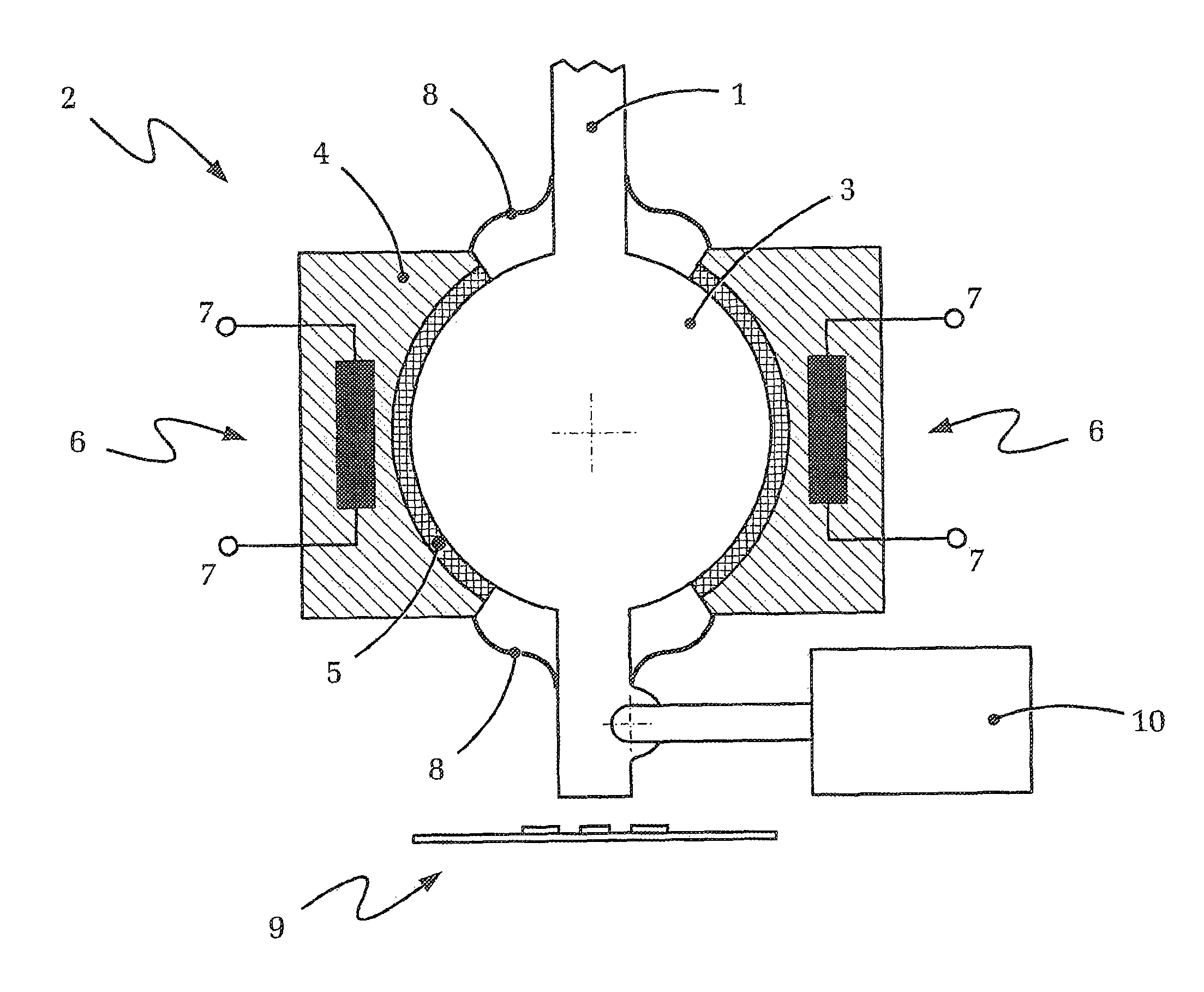
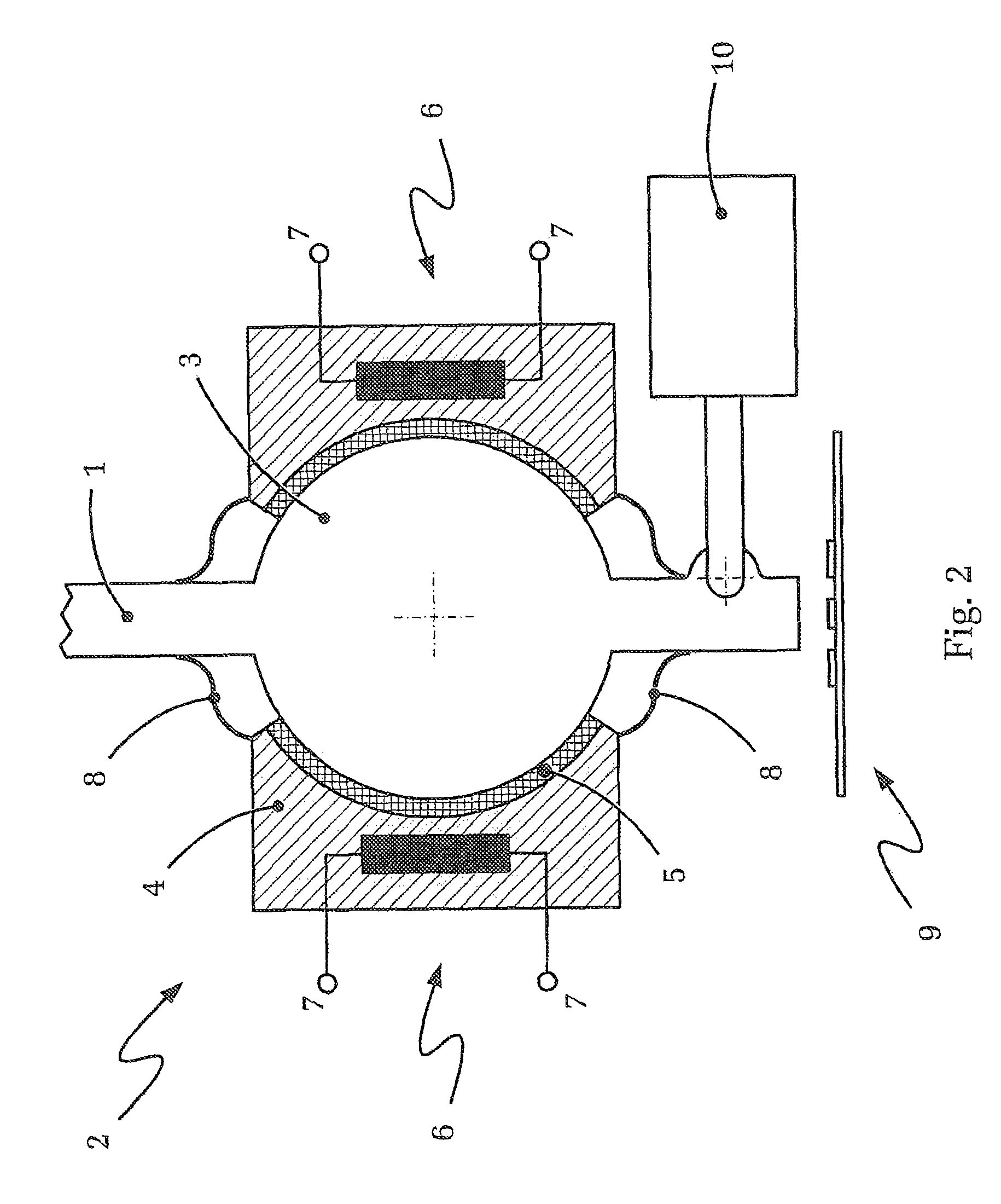
[0048]FIG. 2 shows in a highly schematic diagram a ball joint, which basically corresponds to the ball joint of FIG. 1, of an operating device according to the present invention.

[0049]FIG. 2 shows again an operating lever 1 of which only a portion (its lower region and the joint region, respectively) is illustrated. The operating lever 1 is again connected with an (unillustrated) base of the operating device by way of a bearing constructed in form of a ball joint. The ball joint according to FIG. 2 includes the ball 3 arranged on the operating lever 1 and the ball socket 4 connected with the (unillustrated) base.

[0050]According to the invention, the illustra...


PUM


Abstract

An operating device for a gear-changing transmission operated by shift-by-wire is disclosed. The operating device includes an operating element, rotatably or pivotally supported in a bearing position having a position sensor device, and a device for producing force-feedback. The force-feedback device includes an adjustable counterforce element acting on the operating element, wherein the counterforce element comprises a fluid having controllably variable viscosity. The operating device including the counterforce element is produced by a bearing gap of the bearing position of the operating element, with the bearing gap being filled with the fluid. A space-saving integration of the counterforce element of a force-feedback device is enabled into the joint of an operating lever. Thus, the cost, structural complexity, and installation space required for an operating device having force-feedback is significantly reduced. The haptics of a mechanical operating lever can be realistically emulated.

Description

[0001]This is a continuation application of PCT / DE 2009 / 050020, filed on Apr. 8, 2009 and claiming priority to DE 10 2008 001 805.8, filed on May 15, 2008.BACKGROUND OF THE INVENTION[0002]1. Field of the Invention[0003]The invention relates to an operating device for a gear-changing transmission, example for a gearbox or for an automatic transmission with shift-by-wire operation, according to the preamble of claim 1.[0004]2. Description of Related Art[0005]Gear-changing transmissions for automobiles are generally shifted or controlled with an operating device arranged within the reach of the operator. Typically, operating elements, such as shift levers or selection levers are used which are arranged, for example, between the front seats of the automobile or in other areas of the cockpit.[0006]In particular, it required for ergonomic and safety reasons that presently impermissible shift positions or the execution of the required shifting operations is haptically indicated to the oper...

Claims


Application Information

Patent Timeline
Patent Type & Authority Patents(United States)
IPC IPC(8): B60K17/04B60K17/12B60K20/00F16H59/04
CPCF16H59/0278F16H61/24Y10T74/2003Y10T74/2014F16H2061/241F16C11/0614F16C11/068F16C2210/06F16C2361/65
Inventor RAKE, LUDGERGIEFER, ANDREAS
Owner ZF FRIEDRICHSHAFEN AG
Why Eureka
Try Eureka