
Video signal processing circuit, display device, mobile terminal, and program

a video signal and display device technology, applied in the field of image processing, can solve the problem that the display device cannot perform hue adjustment, and achieve the effect of preventing the degradation of the maximum luminance due to correction processing and maintaining the brightness of the displayed imag

Inactive Publication Date: 2013-04-09
SHARP KK
View PDF5 Cites 0 Cited by
  • Summary
  • Abstract
  • Description
  • Claims
  • Application Information

AI Technical Summary

Benefits of technology

The invention prevents the brightness of TV videos or images from decreasing while still maintaining a realistic color range (0 to 70%). This ensures that there is no degradation in the displayed image.

Problems solved by technology

However, some display devices are not capable of performing hue adjustment (γ correction).

Method used


Image

  • Video signal processing circuit, display device, mobile terminal, and program
  • Video signal processing circuit, display device, mobile terminal, and program
  • Video signal processing circuit, display device, mobile terminal, and program

Examples


first embodiment

[0064]The present embodiment offers the following effects in addition to the effects of the Specifically, the brightness of a displayed image can be maintained also on the high luminance side of the input.

[0065]A “parameter determination method” is described below. The following parameters to be used are set in a register or the like before starting the white processing.

Ax: magnification (1<Ax<∞)

Cx: curvature (0<Cx≦1)

Dx: downward curvature (0≦Dx<1)

(X=R,G,B)  [Expression 6]

[Expression 7]

Y=0.3*R+0.6*G+0.1*B  Equation 2-1

[0066]A correction coefficient (Ax) is determined for the purpose of keeping the luminance of the input and output. Here, R, G, and B are weighted with their respective weighting coefficients each determined based on the degree by which the color contributes to the luminance.

[0067]x indicates any of R, G, or B. Using (Equation 2-1) given above for the equation representing the conversion of RGB to luminance (Y), magnifications (AR, AG, AB) used in principle 2 ca...

second embodiment

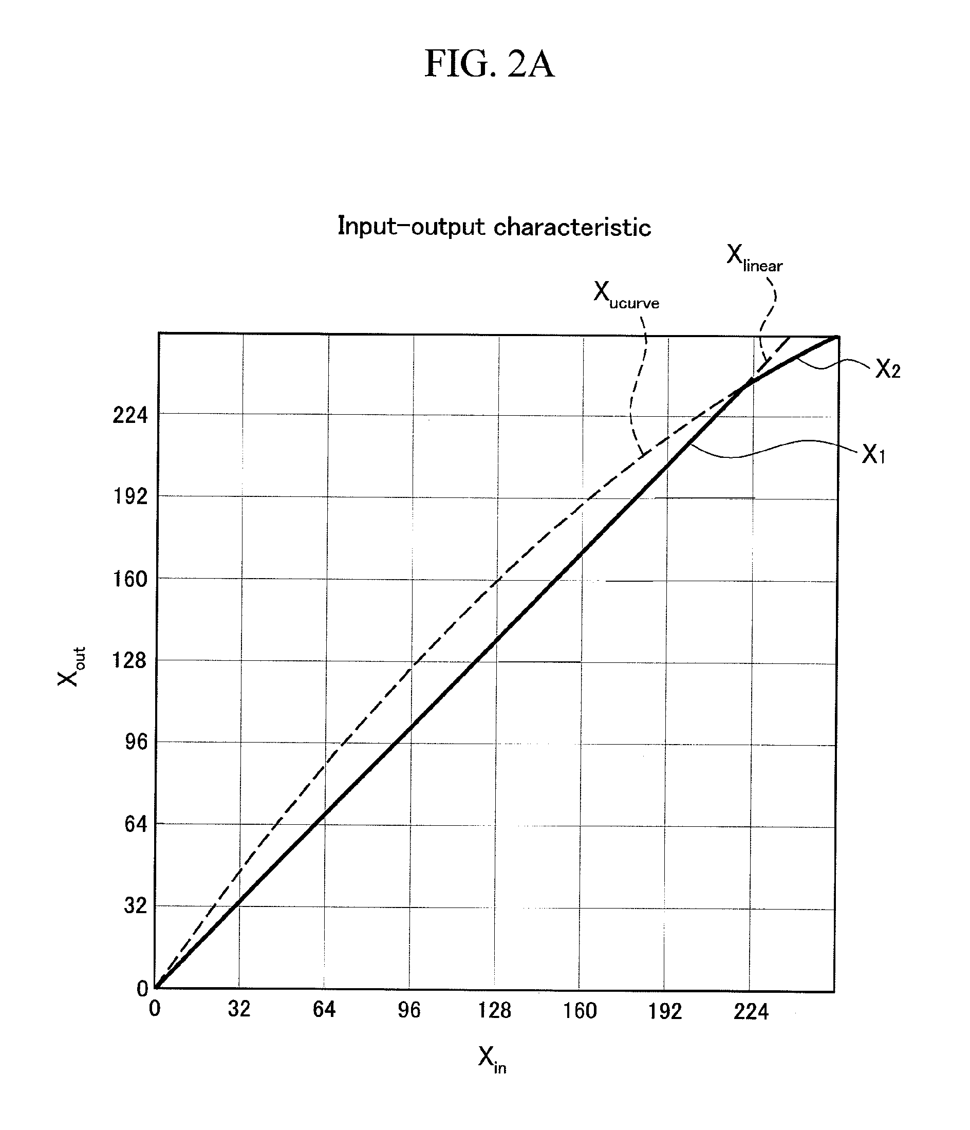
[0115]Next, FIG. 13 shows a flow of processing, directly by software, the functions of the hardware configuration (circuit) of one of the image processing techniques according to the embodiments of the present invention, namely, the functions of the hardware configuration (circuit) shown in FIG. 7. As FIG. 3 shows, the processing starts (START), and in Step S200, arithmetic is performed on Xlinear=Ax·Xin for each of RGB. Next, in Step S201, arithmetic is performed on Xucurve=(1−Cx)·Xin2+Cx·Xin. In Step S202, Ex is obtained as Ex=1 (Axx=Ax (Ax>=0). In Step S203, arithmetic is performed on Xlcurve=(Ex−Dx)·Xin2+Dx·Xin.

[0116]If YES in Step S204, the processing proceeds to Step S205, where Xout=Xlinear is obtained. If NO in Step S204, the processing proceeds to Step S206, where Xout=Xlcurve is obtained.

[0117]Next, in Step S207, whether Xoutucurve or not is determined. If YES, the processing ends (a signal is outputted). If NO, Xout=Xucurve is obtained, and the processing ends (a signal ...


PUM


Abstract

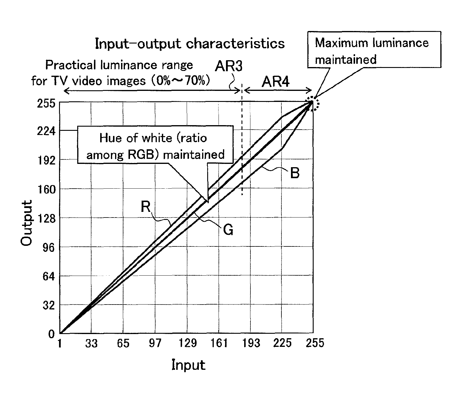
Shown is a diagram showing input-output characteristics for color adjustment. The horizontal axis represents an input, and the vertical axis represents an output. In this color adjustment technique, first, so as to prevent degradation the luminance of white after white correction, correction coefficients are determined so that the smallest value thereof may be 1. Note that “1” here is not a strict value. To be more specific, in contrast to the conventional technique in which correction is performed with the largest value being made equal to about “1,” the present embodiments sets the smallest value at about “1.” This idea itself is a first point which makes the embodiments different from the conventional technique. When doing so, all the correction coefficients are “1” or larger. In the case where a correction coefficient is “1” or larger, when the input is large, the output is saturated. To prevent the saturation, the saturation suppressed using an n-degree curve (Xucurve) which is, for example, a quadratic curve or a cubic curve. If doing so, degradation in the maximum luminance due to correction processing can be suppressed while the hue of white is maintained in a practical luminance range (0 to 70%) for video images of a television receiving set (TV), or the like. Thereby, degradation in the maximum luminance due to correction processing can be suppressed while the hue of white is maintained.

Description

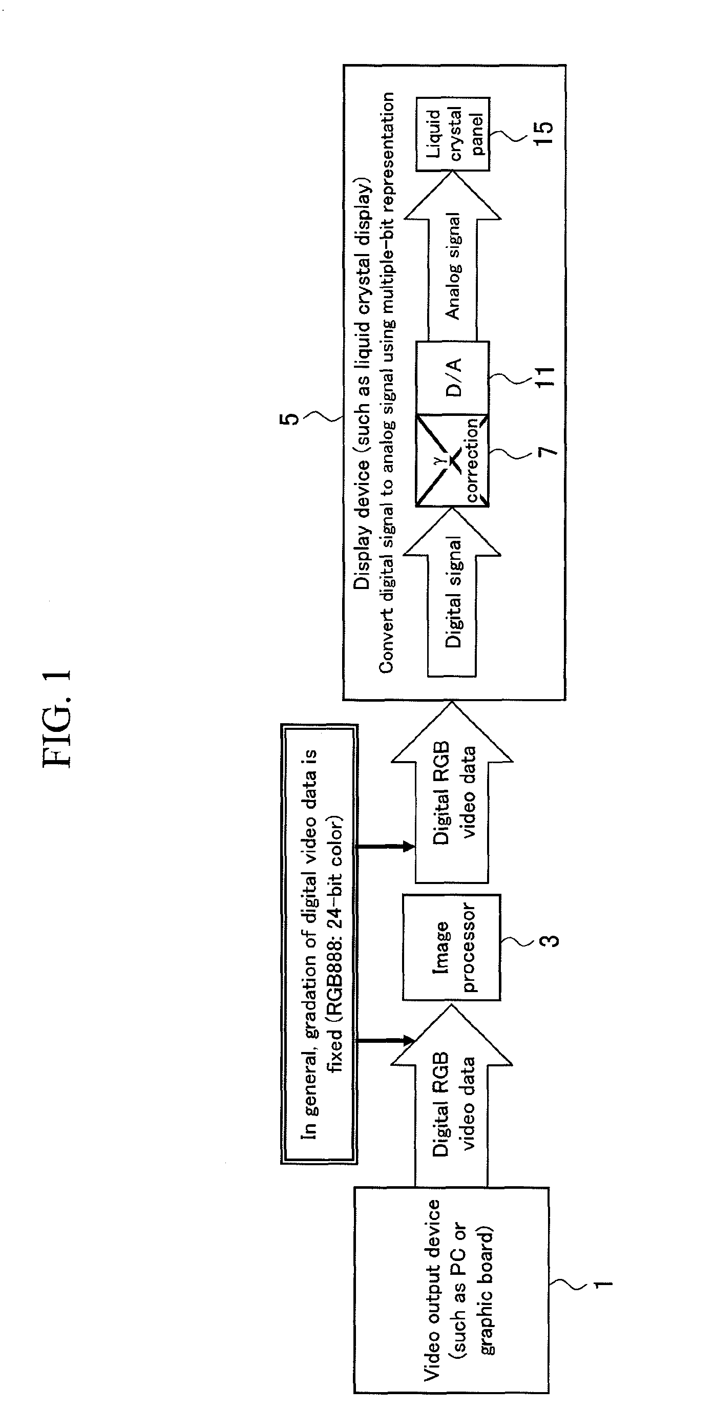
TECHNICAL FIELD[0001]The present invention relates to image processing, and particularly to an image processing technique for facilitating excellent white display.BACKGROUND ART[0002]In color television broadcasting such as NTSC / PAL (EBU), R, G, B chromaticity points and a standard white point are defined for each broadcasting system. A TV video image is adjusted in color based on those defined colors, and then broadcasted. Thus, a predetermined color (white) is expected to be displayed on a display device. When a video image is to be displayed on a display device, such as a liquid crystal display, based on digital RGB video data, a general practice is to cause the display device to perform color adjustment on white through γ correction, and to thereby display the predetermined white.[0003]However, some display devices are not capable of performing hue adjustment (γ correction). In a display device described in Patent Literature 1 given below, RGB video signals are subjected to imag...

Claims


Application Information

Patent Timeline
Patent Type & Authority Patents(United States)
IPC IPC(8): G09G5/02
CPCH04N1/6005H04N1/6027H04N9/73
Inventor MAMBA, OSAMUOTSUKA, KOJIHAGIWARA, YASUFUMIKOYAMA, DAISUKE
Owner SHARP KK
Learn More