Image forming apparatus for setting a velocity difference between a photosensitive drum and an intermediate transfer belt

a technology of image forming apparatus and transfer belt, which is applied in the direction of electrographic process apparatus, instruments, optics, etc., can solve the problems of immoderate shortened image forming unit life, color misregistration generation, and the difference in the velocities of the transfer belt passing through each transfer nip, so as to reduce color registration, shorten the life of the image forming unit, and flexibly suppress the velocity fluctuation of the intermediate transfer belt

Active Publication Date: 2013-04-09
CANON KK
View PDF7 Cites 7 Cited by
  • Summary
  • Abstract
  • Description
  • Claims
  • Application Information

AI Technical Summary

Benefits of technology

[0009]The present invention is directed to reducing color registration without immoderately shortening the life of the image forming unit and by flexibly suppressing velocity fluctuation of the intermediate transfer belt generated while forming an image.
[0011]According to the present invention, color registration can be reduced without immoderately shortening the life of the image forming unit and by flexibly suppressing velocity fluctuation of the intermediate transfer member generated while forming an image.

Problems solved by technology

Further, velocity fluctuation of the intermediate transfer belt causes color misregistration in an image forming apparatus which sequentially activates image forming units including the photosensitive drum.
As a result, a pulling force or a pressing force is applied on the belt between the transfer nips of the image forming units of each color, which causes a difference in the velocities of the belt passing through each of the transfer nips.
Such change in the friction coefficient also causes a change in a tangential force, thus leading to generation of color misregistration.
However, in the above-described method, time for performing the charging and developing processes becomes longer, so that the lifetime of the image forming unit becomes immoderately shortened.

Method used


Image

  • Image forming apparatus for setting a velocity difference between a photosensitive drum and an intermediate transfer belt
  • Image forming apparatus for setting a velocity difference between a photosensitive drum and an intermediate transfer belt
  • Image forming apparatus for setting a velocity difference between a photosensitive drum and an intermediate transfer belt

Examples


Embodiment Construction

[0025]The individual embodiments described below will be helpful in understanding a variety of concepts of the present invention from the generic to the more specific. Further, the technical scope of the present invention is defined by the claims, and is not limited by the following individual embodiments.

[0026]Various exemplary embodiments, features, and aspects of the invention will be described in detail below with reference to the drawings.

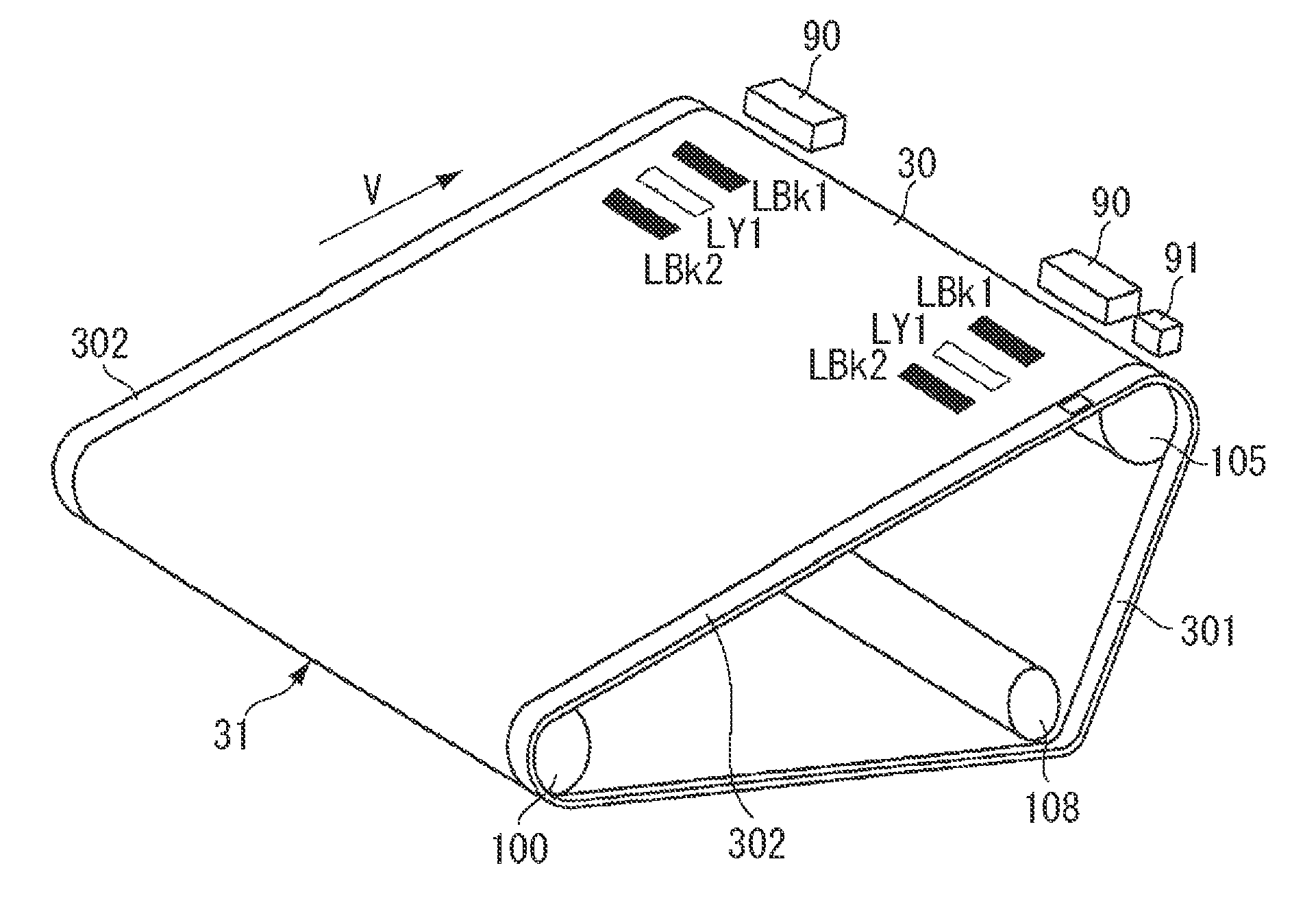
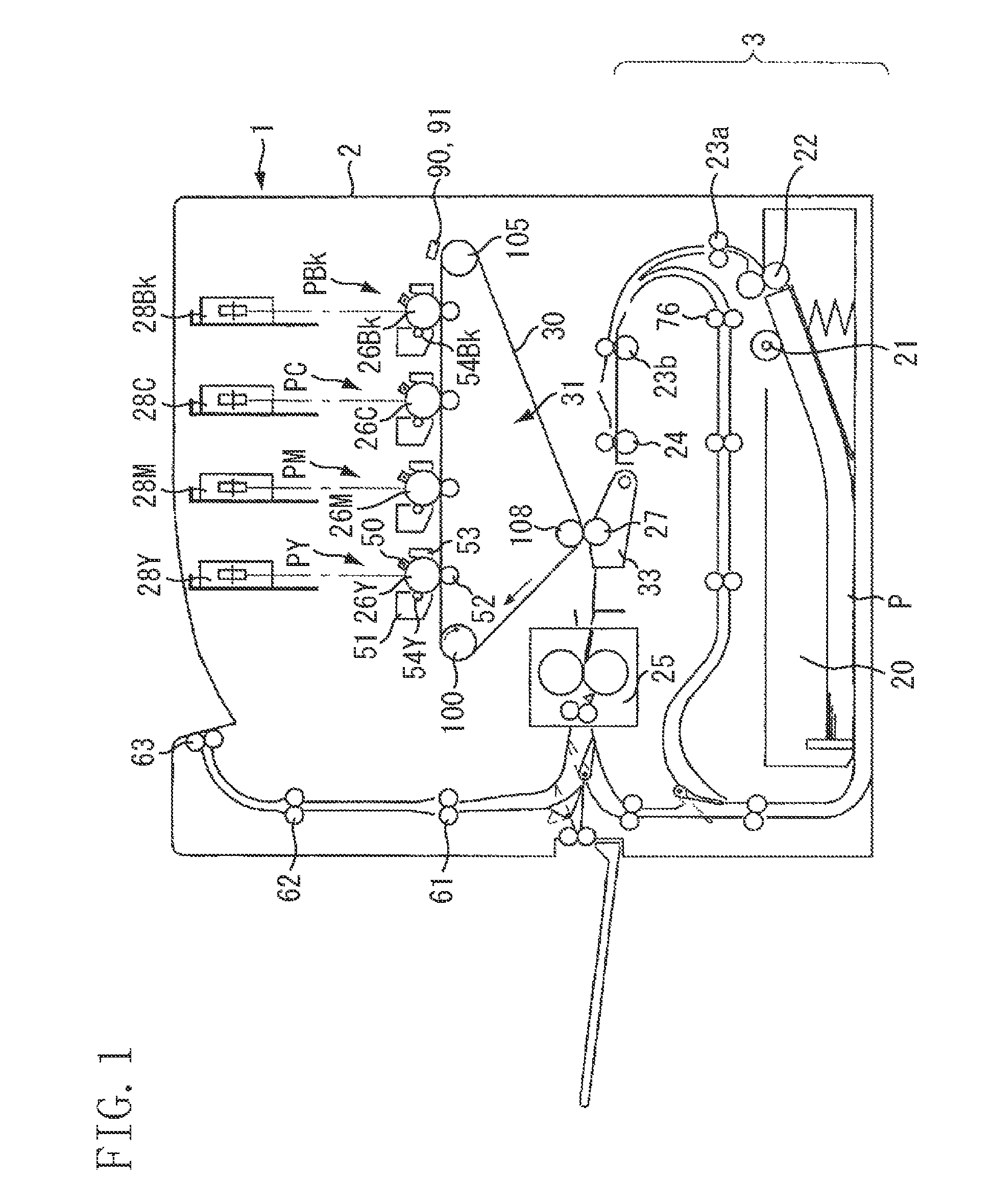
[0027]FIG. 1 is a schematic diagram illustrating a configuration of a four-drum full-color image forming apparatus employing an intermediate transfer belt, among image forming apparatuses according to an exemplary embodiment of the present invention.

[0028]Referring to FIG. 1, a four-drum full-color image forming apparatus 1 includes a four-drum full-color image forming apparatus main body 2 (hereinafter referred to as an apparatus main body 2). The apparatus main body 2 includes process cartridges PY, PM, PC, and Pbk for each of four respectiv...


PUM


Abstract

An image forming apparatus detects a plurality of times by changing velocity of a photosensitive drum, color misregistration generated when a developing roller separates from a photosensitive drum and calculates a relation between the velocity of the photosensitive drum and the color misregistration. A velocity of the photosensitive drum is changed and an arbitrary peripheral velocity difference is set between the photosensitive drum and the intermediate transfer belt based on the calculated result.

Description

BACKGROUND OF THE INVENTION[0001]1. Field of the Invention[0002]The present invention relates to drive control of an image forming apparatus which forms an image on a recording medium.[0003]2. Description of the Related Art[0004]Color misregistration is one of the criteria for determining output image quality of a color image forming apparatus in which high-quality image output is demanded. To reduce such color misregistration, the image forming apparatus may form toner patches of each color on an intermediate transfer belt and detect color misregistration using a registration detection sensor to detect the position of the toner patches. The color image forming apparatus then changes timing of forming each color image on a photosensitive drum based on the detection result.[0005]Further, velocity fluctuation of the intermediate transfer belt causes color misregistration in an image forming apparatus which sequentially activates image forming units including the photosensitive drum. I...

Claims


Application Information

Patent Timeline
Patent Type & Authority Patents(United States)
IPC IPC(8): G03G15/00
CPCG03G15/0131G03G15/1615G03G15/5054G03G15/5058G03G2215/00059G03G2215/0129G03G2215/0161
Inventor MATSUO, TAKAMICHI
Owner CANON KK
Why Eureka
Try Eureka