

Plasma igniter and ignition device for internal combustion engine
a technology of internal combustion engine and igniter, which is applied in the direction of sparking plugs, machines/engines, mechanical equipment, etc., can solve the problems of difficult implementation of efficient ignition and combustion, small amount of generated active radical species, etc., and achieve the effect of improving the air-fuel ratio (a/f) and reducing the amount of co2 emissions
Inactive Publication Date: 2013-04-16
NGK INSULATORS LTD
View PDF25 Cites 16 Cited by
- Summary
- Abstract
- Description
- Claims
- Application Information
AI Technical Summary
Benefits of technology
[0006]It is considered to take measures against the above problem by enlarging a plug gap of the SI plug. When the SI plug having the large plug gap is used, the discharge region is enlarged, so that the ignition can be surely expected. However, when the plug gap was enlarged too much, it was necessary to apply a high voltage to ensure the ignition. That is, when the internal-combustion engine (igniter) is operated by use of the conventional SI plug, the discharge region can be enlarged (or reduced) only by enlarging (or reducing) the plug gap of the SI plug, so that a degree of freedom of application is low, and there is a case where it cannot be preferably applied to an ignition and combustion method in which a pulse voltage is applied to generate non-equilibrium plasma for ignition.
[0007]The present invention has been made in view of the problem in the background technique, and it is an object of the present invention to provide a plasma igniter capable of generating a discharge such as a pulse streamer discharge in a large region even by application of a low voltage, implementing powerful ignition by pulse voltage application in two or more stages, improving an air-fuel ratio (A / F), and reducing a CO2 emission amount.
[0023]A plasma igniter and an ignition device for an internal-combustion engine can generate a discharge such as a pulse streamer discharge in a large region even by application of a low voltage, implement powerful ignition by pulse voltage application in two or more stages, improve an air-fuel ratio (A / F), and reduce a CO2 emission amount.
Problems solved by technology
Meanwhile, when it is assumed that the pulse voltage is applied between the electrodes at predetermined intervals several times repeatedly with the general SI plug to generate non-equilibrium plasma containing active radical species to implement ignition, there is a problem that the generated active radical species is small in amount and it is difficult to implement efficient ignition and combustion because a discharge region is limited to the space between the center electrode and the ground electrode.
However, when the plug gap was enlarged too much, it was necessary to apply a high voltage to ensure the ignition.
Method used
View moreImage
Smart ImageViewing Examples

Examples
example 1
[0114]The discharge part 10 having the configuration shown in FIG. 14 was mounted on a single-cylinder 250 cc gasoline engine. A mixture gas was ignited and burnt by applying pulse voltages in such a manner that a voltage of 18 kV was applied nine times and a voltage of 20 kV was applied one time. A schematic view showing a chronological change while the pulse voltages were applied to the discharge part is shown in FIG. 18.
Login to View More PUM
 Abstract
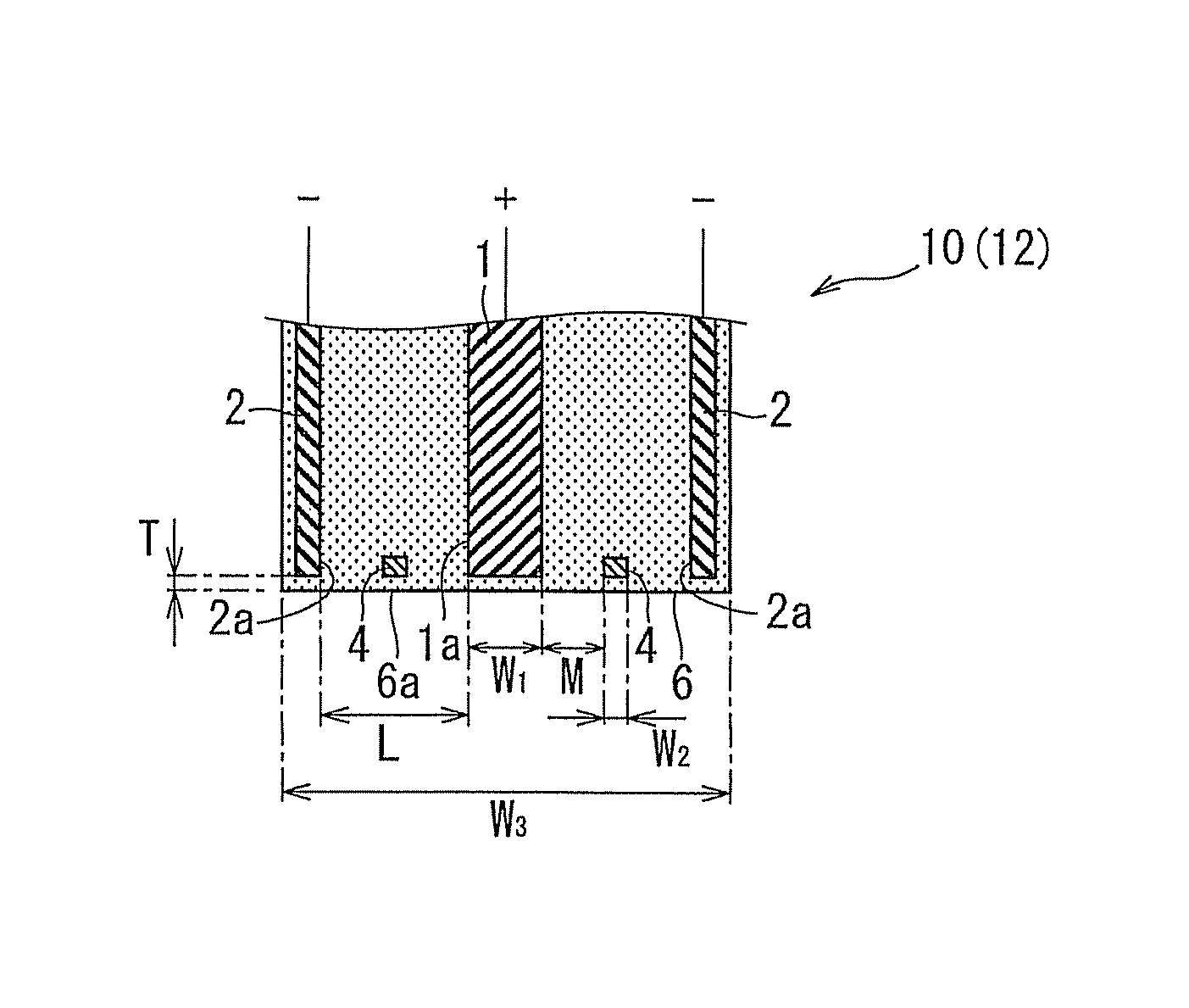
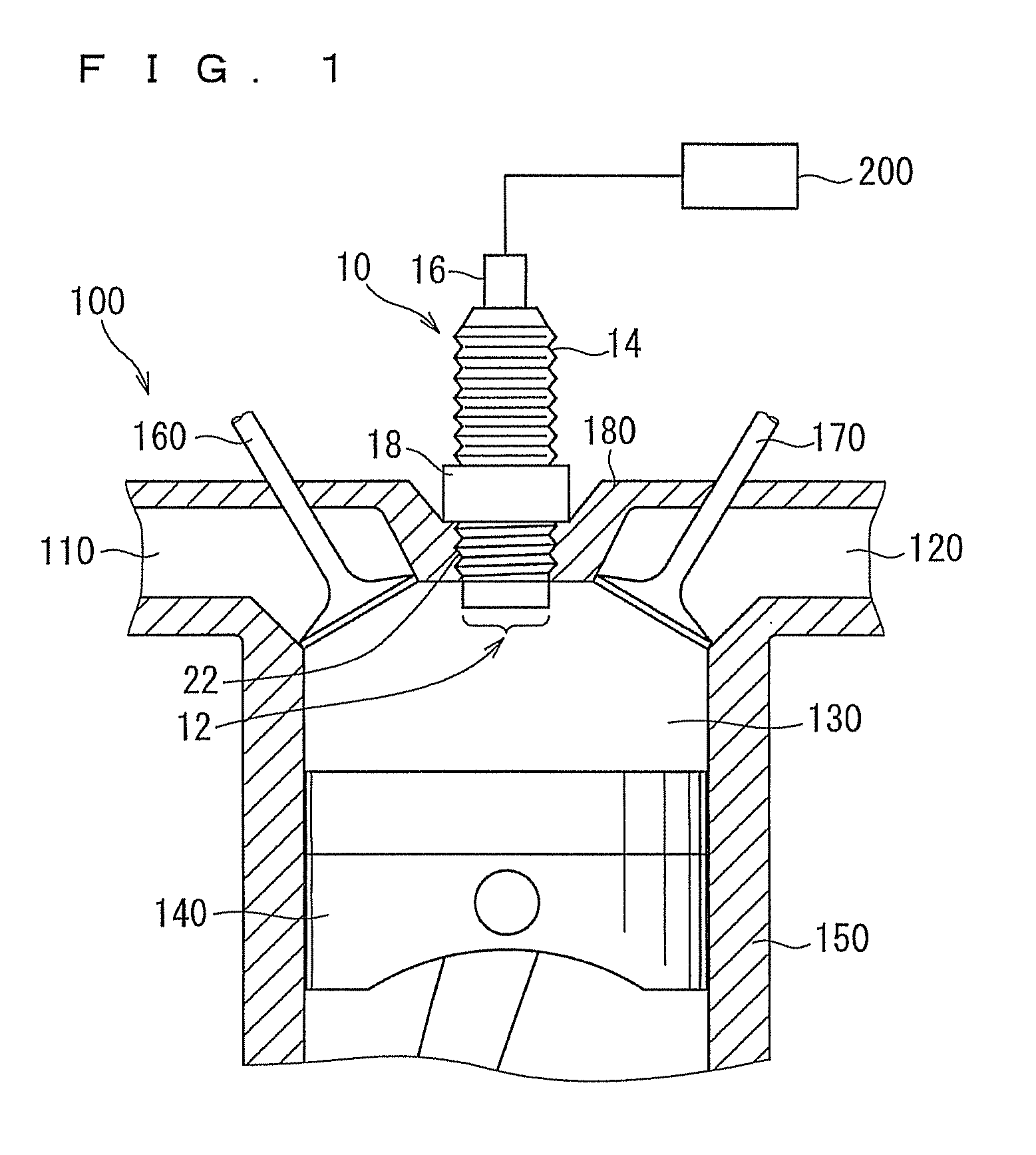
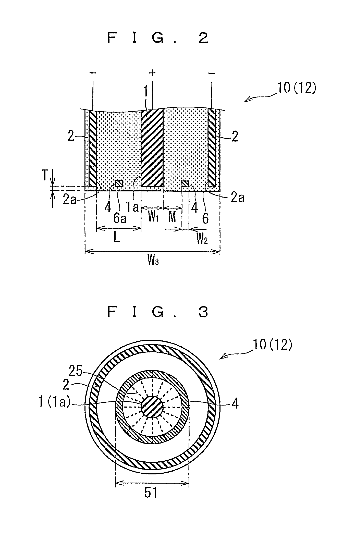
To provide a plasma igniter capable of generating a discharge such as a pulse streamer discharge in a large region even by application of a low voltage, implementing powerful ignition by pulse voltage application in two or more stages, improving an air-fuel ratio (A / F), and reducing a CO2 emission amount.A plasma igniter includes an igniter part having a combustion chamber, and a discharge part arranged in such a manner that its discharge tip end is exposed to the combustion chamber. The discharge tip end has a column-shaped anode, an annular cathode arranged to be a predetermined interval away from an anode tip end part, and an annular floating electrode arranged between the anode tip end part and the cathode.
Description
FIELD OF THE INVENTION[0001]The present invention relates to a plasma igniter suitable for an internal-combustion engine such as a gasoline engine, and an ignition device for the internal-combustion engine.BACKGROUND OF THE INVENTION[0002]Conventionally, at the time of engine ignition, a method of igniting a mixture gas using a spark plug (spark injection (SI) plug) is employed (see patent document 1, for example). The SI plug is a well-known electric component used to ignite the mixture gas in a combustion chamber of an engine, and generally includes a center electrode, an insulator provided around an outer circumference of the center electrode, a mounting screw part provided around an outer circumference of the insulator and mounted on the engine, and a ground electrode connected to an end part of the mounting screw.[0003]When a high voltage is applied between the center electrode and the ground electrode of the SI plug, insulation between the electrodes is destroyed and a dischar...
Claims
Login to View More Application Information
Patent Timeline
 Patent Type & AuthorityPatents(United States)
IPC IPC(8): F02B5/02F02P3/01
CPCF02P9/007F02P15/02F02P23/04H01T13/462H01T13/50H01T13/54
InventorSHIMIZU, NAOHIRO
OwnerNGK INSULATORS LTD