
Decorative disposer flange and strainer assembly

a technology of disposer flange and strainer assembly, which is applied in the direction of gas current separation, washing stand, grain treatment, etc., can solve the problems of difficult removal, rotting smell from the sink, and awkward or out of place stainless steel flanges that do not often match the finish of the sink,

Inactive Publication Date: 2013-04-23
OPELLA
View PDF14 Cites 42 Cited by
  • Summary
  • Abstract
  • Description
  • Claims
  • Application Information

AI Technical Summary

Benefits of technology

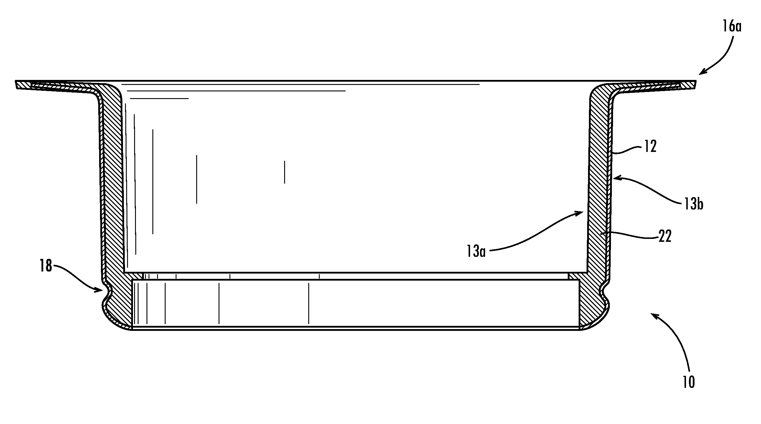
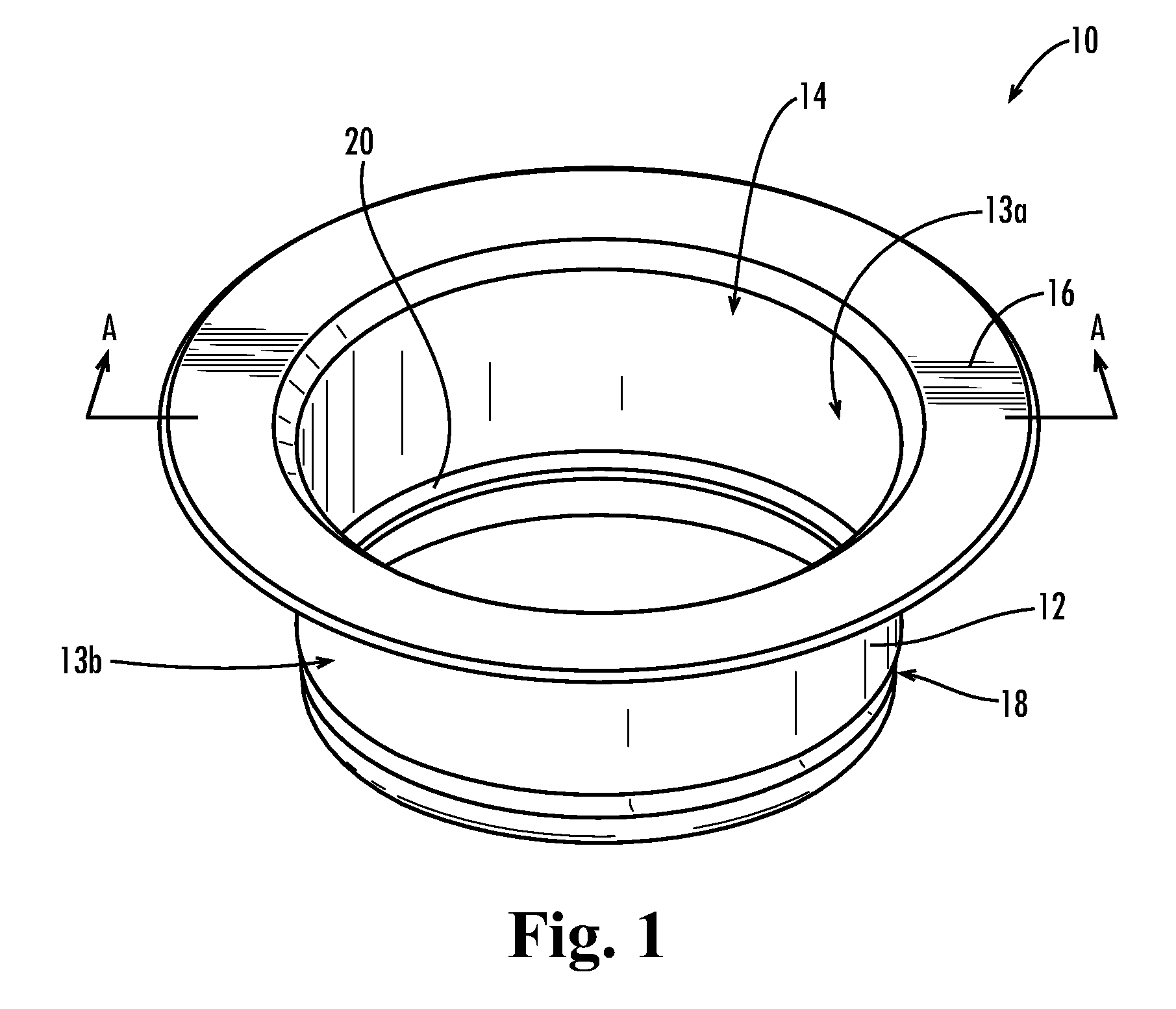
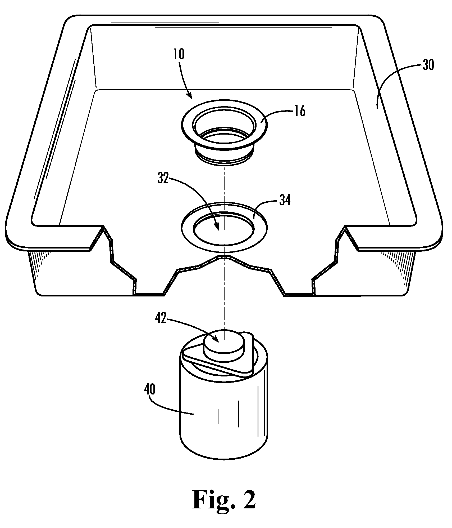
The present invention relates to a sink flange that is used with a sink drain. The flange has a vertical body with a top end and a bottom end, and a lip that extends out from the top end. The flange lip has a top side and a bottom side, and is coated with a strong and durable impact resistant polymer. The flange body can be made from stainless steel or other durable materials, and the polymer coating can be customized to match or complement the user's kitchen decor. This invention provides a decorative flange that is both strong and durable, allowing users to customize its appearance to match their own or complement the overall decor of their kitchen. Additionally, the invention includes a strainer assembly with the same color as the sink flange, which can be coated with the plastic resin as well. Another improvement involves applying a thermoplastic coating to at least one surface of the flange, which can be applied to the flange lip or the flange passage.

Problems solved by technology

Therefore, the supplied stainless steel flange does not often match the finish of the sink and can look awkward or out of place.
Food caught between the two surfaces can cause a rotting smell to emanate from the sink and can be very difficult to remove.
Additionally, food caught between the two surfaces can cause an unsanitary condition to develop.
Once the powder coat is chipped, the flange cannot be repaired and must be replaced.

Method used


Image

  • Decorative disposer flange and strainer assembly
  • Decorative disposer flange and strainer assembly
  • Decorative disposer flange and strainer assembly

Examples


Embodiment Construction

[0014]The present invention may be understood more readily by reference to the following detailed description of the invention taken in connection with the accompanying drawing figures, which form a part of this disclosure. It is to be understood that this invention is not limited to the specific devices, methods, conditions or parameters described and / or shown herein, and that the terminology used herein is for the purpose of describing particular embodiments by way of example only and is not intended to be limiting of the claimed invention. Also, as used in the specification including the appended claims, the singular forms “a,”“an,” and “the” include the plural, and reference to a particular numerical value includes at least that particular value, unless the context clearly dictates otherwise. Ranges may be expressed herein as from “about” or “approximately” one particular value and / or to “about” or “approximately” another particular value. When such a range is expressed, another...


PUM


Abstract

A sink flange for use in conjunction with a sink drain. The flange includes a flange body and a flange lip. The flange body is substantially vertical having a top end and a bottom end. The bottom end defines a flange passage therethrough. The flange lip is annular having a top side and a bottom side, which radially extends out of the top end of the flange body. The flange passage and flange lip are at least coated with a polymer.

Description

TECHNICAL FIELD[0001]The present invention relates generally to the field of garbage disposers and more particularly, to decorative disposer flanges and strainer assemblies.BACKGROUND OF THE INVENTION[0002]Garbage disposers are typical kitchen devices that are generally stored under the sink between the sink's drain and trap. The disposers shred food waste into very small pieces so that it can be passed through the plumbing without clogging. Typically, a garbage disposer is supplied with a sink flange that fits into the topside of the sink. The flange connects to the disposer below and provides a finished appearance to the sink drain. Additionally, the flange provides a reliable connection to the disposer and helps prevent water from leaking around the sink's drain.[0003]Traditionally, residential sinks have been provided having a stainless steel finish. More recently, however, sinks have become available in a variety of colors and finishes to match the decor of a particular kitchen...

Claims


Application Information

Patent Timeline
Patent Type & Authority Patents(United States)
IPC IPC(8): A47K1/14
CPCB02C18/0092E03C1/22E03C1/266
Inventor SVENSSON, RON
Owner OPELLA
Learn More