Cord lock assembly

a cord lock and assembly technology, applied in the field of cord locks, can solve the problems of affecting the use of the teeth to pull the draw cord tight, wear the draw cord, and is difficult to feel, grip, grasp and manipulate the cord lock, etc., to reduce the pinching force of the cord lock

Active Publication Date: 2013-04-23
ILLINOIS TOOL WORKS INC
View PDF25 Cites 14 Cited by
  • Summary
  • Abstract
  • Description
  • Claims
  • Application Information

AI Technical Summary

Benefits of technology

[0013]Embodiments of the present invention provide a cord lock assembly that may be operated with one hand. Embodiments of the present invention provide a cord lock assembly that reduces the pinching force of the cord lock on the draw cord during tightening, and provides a release mechanism that releases the pinch on the draw cord and spreads the opening during loosening. Further, embodiments of the present invention provide a cord lock assembly that may have a compact, rounded shape that is easy to feel, grip, grasp and manipulate even while wearing gloves or mittens.
[0019]The cord lock assembly also includes a piston slidably retained within the interior chamber of the shell. The piston may include a piston cord passage formed therethrough. The cross-section (or cross-sectional envelope) of the piston may also be shaped as an oval. The oval shape of the piston with the oval shell ensures that the piston does not rotate within the shell. Also, the oval shape provides strength to the cord lock assembly.
[0024]The shell of the cord lock assembly may include first and second open ends. A flexible lanyard may be anchored over one of the first and second open ends. The flexible lanyard may limit the movement of the piston (e.g., prevent the piston from ejecting from the shell), while at the same time assisting in aligning the passages when the cord is pulled.

Problems solved by technology

In the case of using the system to seal the cuffs of gauntlet style gloves or mitts, where only one hand is available for adjustment, using the teeth to pull the draw cord tight is typically awkward.
This takes effort, prematurely wears the draw cord, wears the cord passage pinching edges, overstretches the shock cord when used and stresses the anchor points.
Squeezing the draw cord between the tips of the thumb and the forefinger makes it more difficult to keep a good grip when pulling outward at the same time.
Such an operation is also not easy to perform while wearing gloves or mittens, particularly if they are heavily insulated.
Although some cord locks include defined gripper squeezing surfaces, these surfaces are typically large and obtrusive.
As such, they are susceptible to impact damage and entanglement with various other items exterior to the cord lock.

Method used


Image

  • Cord lock assembly
  • Cord lock assembly
  • Cord lock assembly

Examples


Embodiment Construction

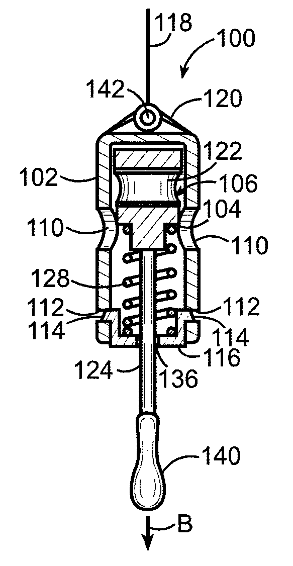
[0051]FIG. 11 illustrates an isometric view of a glove 90 having a cord lock assembly 100 that is configured to selectively expand and tighten an opening 92 of a cuff of the glove 90, according to an embodiment of the present invention. The opening 92 allows a wearer to insert his / her hand into the glove 90. A draw cord 94 is positioned within a channel 96 of the cuff of the glove 90 proximate the opening 82. A portion of the draw cord 94 is also retained within the cord lock assembly 100. While the cord lock assembly 100 is shown used with the glove 90, the cord lock assembly 100 may be used with various other items that are configured to be selectively expanded and tightened around an object (such as a waistband of shorts or pants, bags / sacks or the like).

[0052]FIG. 12 illustrates an isometric exploded view of the cord lock assembly 100, according to an embodiment of the present invention. The cord lock assembly 100 may be molded of a rigid plastic, such as acetal, or any other su...


PUM


Abstract

A cord lock assembly is configured to selectively tighten and loosen a draw cord of an article. The cord lock assembly may include a shell, a piston and a spring member. The shell defines an interior chamber and includes aligned shell cord passages. The piston is slidably retained within the interior chamber. The piston includes a piston cord passage formed therethrough. The spring member exerts a force into the piston within the shell so that the piston cord passage is misaligned with respect to the shell cord passages in a locked position. A cord may be operatively secured to the piston and may be configured to be pulled to move the piston to align the piston cord passage with the shell cord passages in an unlocked position so that a draw cord may freely pass therethrough.

Description

RELATED APPLICATIONS[0001]The present application is national phase of PCT / US2008 / 069421 filed Jul. 8, 2008, and claims priority from U.S. Application No. 60 / 959,769 filed Jul. 17, 2007, the disclosures of which are hereby incorporated by reference herein in their entirety.FIELD OF THE INVENTION[0002]Embodiments of the present invention generally relate to draw cords that may be used with outdoor clothing and accessories, and more particularly to an improved cord lock that may be operated with one hand to tighten and loosen draw cords.BACKGROUND OF THE INVENTION[0003]Typical draw cords are contained in a textile tube or channel that encircles an opening. When the draw cord is pulled tight through an exit hole of the channel, the draw cord collapses the channel to close the opening completely, as with a bag opening. The closing is typically just close enough to seal out elements, as with the cuff of a glove or an equipment cover, while allowing adjustment to fit, as with a waist area...

Claims


Application Information

Patent Timeline
Patent Type & Authority Patents(United States)
IPC IPC(8): F16G11/00F16G11/10
CPCA43C1/00A43C1/06F16G11/10A43C7/00Y10T24/3984F16G11/101A43C7/08A43B11/00
Inventor GAMMELL, ROBERT A.KOLASA, SCOTT D.
Owner ILLINOIS TOOL WORKS INC
Why Eureka
Try Eureka