Combined-cycle power plant with exhaust gas recycling and CO2 separation, and method for operating a combined cycle power plant

a combined cycle and power plant technology, applied in the direction of steam generation using hot heat carriers, steam boiler components, lighting and heating apparatus, etc., can solve the disadvantages of reducing the generated output associated with cosub>2 /sub>separation, disadvantages of a gas turbine comparatively low cosub>2 content, etc., and achieve the effect of increasing the output of supplementary firing and reducing the proportion of recycled exhaust gases

Inactive Publication Date: 2013-04-23
GENERAL ELECTRIC TECH GMBH
View PDF15 Cites 73 Cited by
  • Summary
  • Abstract
  • Description
  • Claims
  • Application Information

AI Technical Summary

Benefits of technology

[0009]One of numerous aspects of the present invention includes a combined cycle power plant of the above-described type in which the exhaust gas recycling can be reduced without significant losses in CO2 concentration, and at the same time the generated output can be increased, and also a method for operating such a combined cycle power plant.
[0010]Another of these numerous aspects includes that a supplementary firing is associated with the heat recovery steam generator, which by combusting a carbonaceous fuel produces additional exhaust gases with CO2 content and transmits the exhaust gases through the heat recovery steam generator. The combination of exhaust gas recirculation or exhaust gas recycling and supplementary firing in this case can be used in two different ways. In the first case, the aim is to increase the generated output with the supplementary firing and to reduce the rate of the recycled exhaust gas. The reduction in this case can go to zero in the extreme case. If a recycling of the exhaust gas is permanently dispensed with, the exhaust gas recycling line which is provided for it can even be omitted. In the second case, a flexible operating concept is achieved, which enables a balance between output and efficiency during the CO2 separation.
[0011]Another aspect of a combined cycle power plant embodying principles of the present invention includes that the supplementary firing is integrated into the heat recovery steam generator. As a result of this, an especially compact construction is achieved.

Problems solved by technology

The comparatively low CO2 content in the exhaust gas of a gas turbine is disadvantageous if it involves the separation of CO2 from the exhaust gas.
In the case of this type of augmented concentration of CO2, the high equipment cost of exhaust gas ducts and heat exchangers which is associated with the recycled exhaust gas flow at a recirculation rate of about 50%, and also the reduction of generated output which is associated with the CO2 separation, is disadvantageous.

Method used


Image

  • Combined-cycle power plant with exhaust gas recycling and CO2 separation, and method for operating a combined cycle power plant
  • Combined-cycle power plant with exhaust gas recycling and CO2 separation, and method for operating a combined cycle power plant
  • Combined-cycle power plant with exhaust gas recycling and CO2 separation, and method for operating a combined cycle power plant

Examples


Embodiment Construction

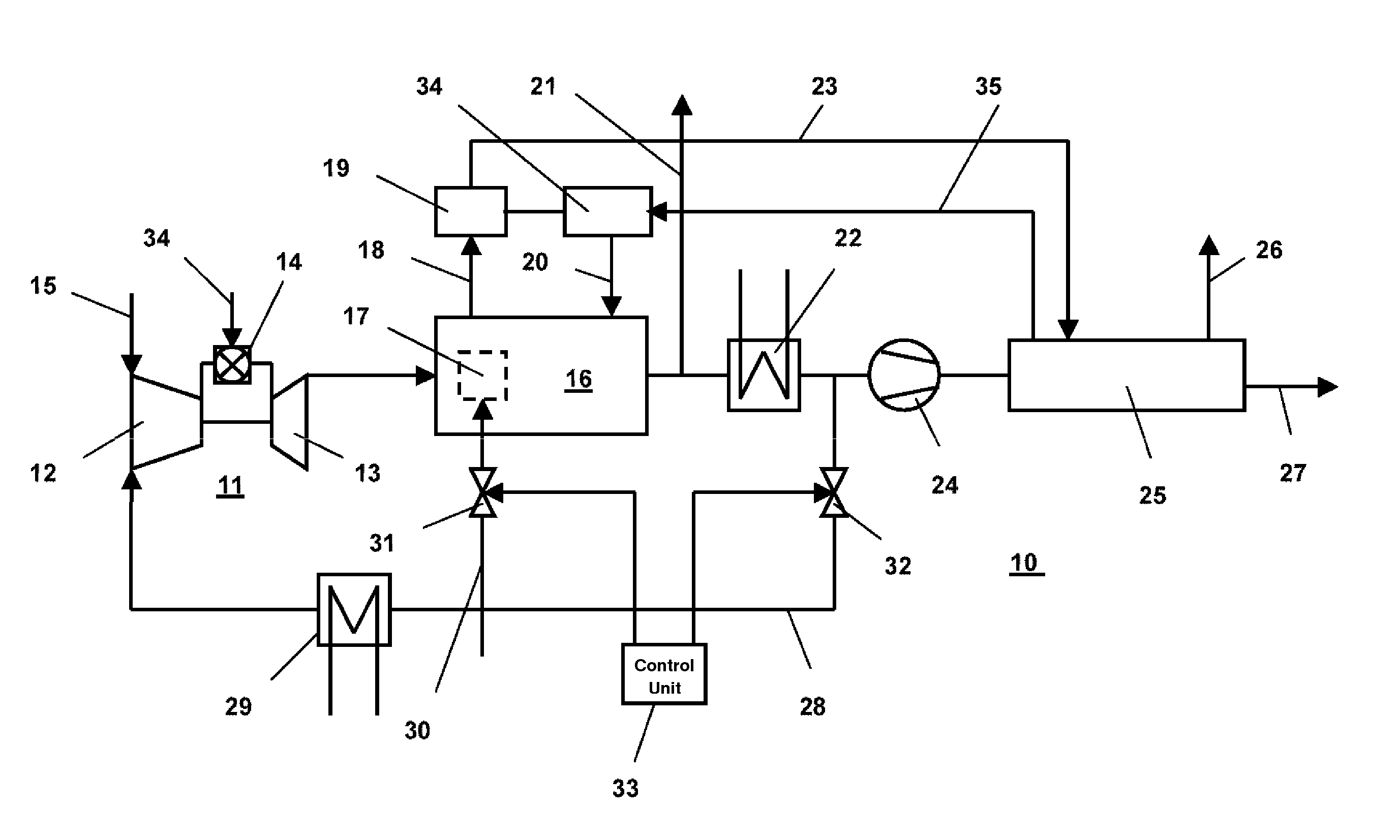
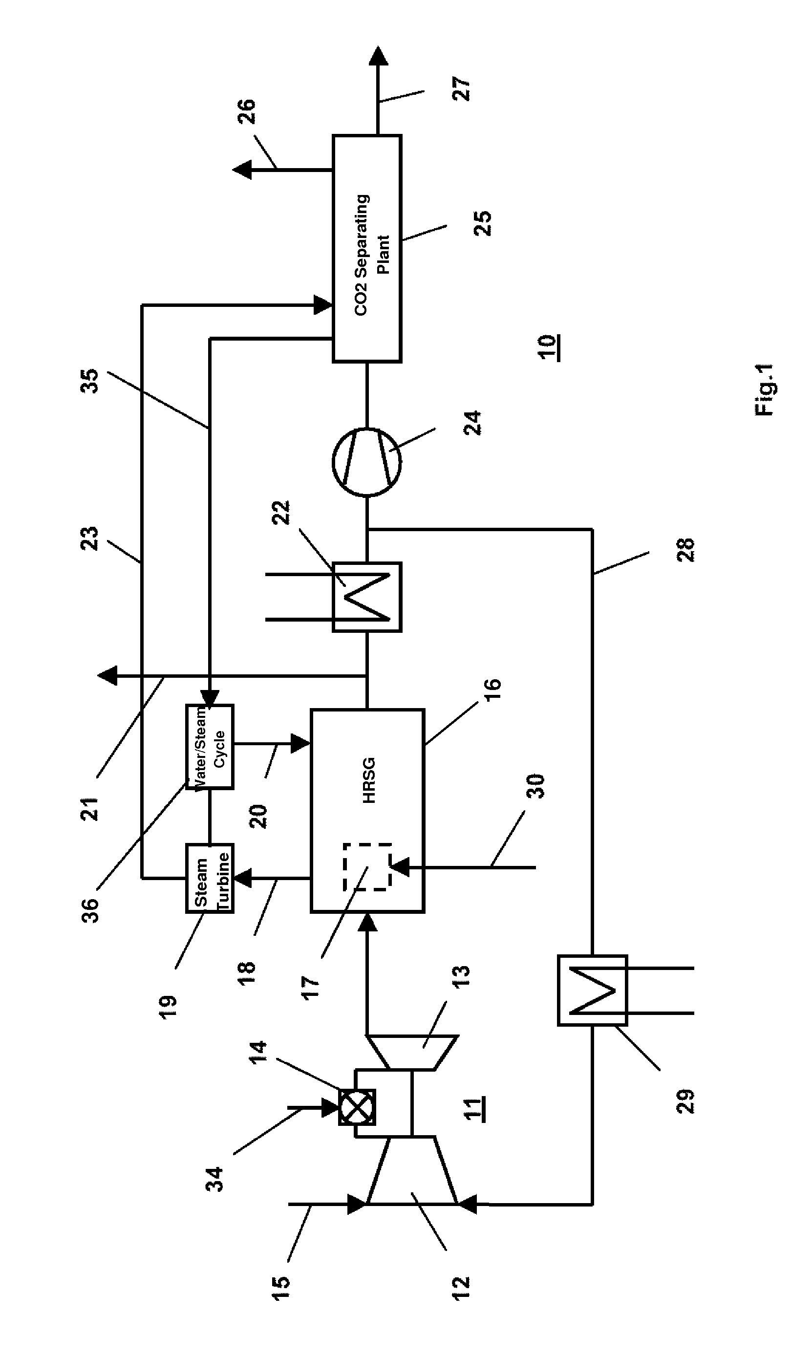
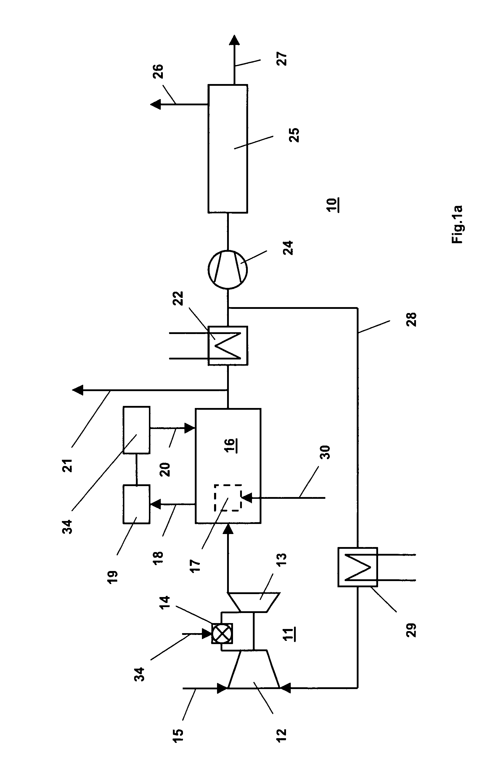
[0029]In FIG. 1, a combined cycle power plant 10 with supplementary firing according to a first exemplary embodiment of the invention is reproduced in a much simplified layout plan. A supplementary firing 17 is integrated in this case in the heat recovery steam generator 16 which is connected downstream to the gas turbine 11, which supplementary firing combusts a carbonaceous fuel which is fed via the fuel feed line 30, reheats the exhaust gas flow which is guided through the heat recovery steam generator 16, and adds to it additional exhaust gas with CO2 content. Without the supplementary firing 17, the exhaust gas discharges from the heat recovery steam generator, for example, at a temperature of 100° C. and is cooled down to 50° C. in the subsequent heat exchanger. Half of the cooled-down exhaust gas flow (recirculation rate of 50%) is then returned via the exhaust gas return line 28 to the inlet of the gas turbine 11 and in doing so is cooled still further to 25° C. in the heat ...


PUM


Abstract

A combined cycle power plant (10) has a gas turbine (11), a heat recovery steam generator (16) which is connected downstream to the gas turbine (11) and delivers steam to a steam turbine (19), an exhaust gas recycling line (28) which returns some of the exhaust gases, which flow from the exhaust of the gas turbine (11) through the heat recovery steam generator (16), to the inlet of the gas turbine (11), and also a CO2 separating plant (25) which separates from the non-returned part of the exhaust gases the CO2 which is contained therein and delivers it to a CO2 outlet. A reduction of the equipment cost or a flexible adaptation of the operation can be achieved by a supplementary firing (17) being associated with the heat recovery steam generator (16), which by combusting a carbonaceous fuel produces additional exhaust gases with CO2 content and transmits them through the heat recovery steam generator (16).

Description

[0001]This application claims priority under 35 U.S.C. §119 to Swiss application no. 01889 / 07, filed 6 Dec. 2007, the entirety of which is incorporated by reference herein.BACKGROUND[0002]1. Field of Endeavor[0003]The present invention refers to the field of power generation. It relates to a combined cycle power plant and to a method for operating a combined cycle power plant.[0004]2. Brief Description of the Related Art[0005]The comparatively low CO2 content in the exhaust gas of a gas turbine is disadvantageous if it involves the separation of CO2 from the exhaust gas. It is known from the prior art (see for example publications EP-A2-1 752 616 or DE-T5-102 97 365), in combined cycle power plants with heat recovery steam generators, to return exhaust gases which come from the gas turbine to the inlet of the gas turbine, after flowing through the heat recovery steam generator, in order to both increase the CO2 content and to reduce the mass flow which has to be processed in the dev...

Claims


Application Information

Patent Timeline
Patent Type & Authority Patents(United States)
IPC IPC(8): F01K23/10F02C6/18
CPCF01K23/103F02C6/006F02C3/34Y02E20/16Y02E20/32
Inventor VOLLMER, MICHAELPEDRETTI, CAMILLEKJELLBERG, TOBIAS
Owner GENERAL ELECTRIC TECH GMBH
Why Eureka
Try Eureka