Spinal fixation device

a fixation device and spine technology, applied in the direction of ligaments, prostheses, osteosynthesis devices, etc., can solve the problems of affecting the healing effect of the spine, so as to reduce the irritation of the abutting and adjacent tissu

Active Publication Date: 2013-04-23
WESTMARK MEDICAL
View PDF132 Cites 15 Cited by
  • Summary
  • Abstract
  • Description
  • Claims
  • Application Information

AI Technical Summary

Benefits of technology

[0005]A fixation plate is provided for tying together or fixing together two or more adjacent cervical vertebrae C2 through T1. The fixation plate can have any of three basic configurations, the first of which resembles an H shape or a series of stacked H shapes, the second of which resembles an A shape or a series of stacked A shapes, and the third of which resembles an X shape or a series of stacked X shapes. Each of the fixation plates is curved or angles about the axial plate through the two adjacent and joined vertebrae at an angle □ that varies with the location on the cervical column and with the number of vertebrae fixed to the plate. The angle is preferably selected to follow the average spinal curvature for the appropriate cervical location, but the angle can be varied according to an individual's specific spinal curvature, and preferably the angle is custom bent prior to use to match the spinal curvature of the patient / user. Each of the fixation plates is also curved or angled at an angle α about the sagittal plane in the anterior direction so the lateral portions of the fixation plate conform to the lateral curvature of the vertebrae and thus allow a more conforming fit of the fixation plate to the vertebrae and a lower profile plate that can fit beneath the tissue covering the anterior of the spine and thereby reduce irritation of abutting and adjacent tissue.
[0006]Each fixation plate has a socket with a curved surface configured to accommodate a bushing having a base with an outwardly extending flange. The bone screw passes through and is held by the bushing. The bushing's flange fits inside an annular recess in a socket of the fixation plate but the recess is slightly larger than the flange so the bushing can tilt until the flange hits the recess. By varying the dimensions of the flange on the bushing and the recess in the socket varying amounts of angulation or angular tilt of the bushing and bone screw can be accommodated. The annular bushing has a slot through it so it can be compressed and inserted into the socket and recess. The annular bushing is thus advantageously a split bushing.
[0008]The screw head can thus rotate inside the bushing, which rotates the socket to allow positioning adjustment of the screw relative to the fixation plate. When the plate is installed, the limited rotation allowed by the screw head, bushing and socket allow impact forces to be accommodated and provide some flexibility in absorbing the impact accompanying those forces. In particular, the split bushing can rotate, translate and distort to a limited degree in absorbing and transmitting forces from the bone screw to the fixation plate.
[0009]The fixation plate is not a solid rectangular plate but has the sockets on the ends of legs. The legs are stiff, but provide more flexibility than does the continuous plate, further providing flexibility and limited motion sufficient to accommodate impact forces. Fixation plates having an H shape, an X shape and an A shape are believed suitable.
[0010]The legs extend from the cross-members of these H and A shaped fixation plates, and from the cross member formed by the four intersecting legs of the X shaped fixation plate. The cross-member and optionally portions of the adjoining legs can be flattened on the posterior side to reduce the profile of the fixation plate and to reduce irritation of adjacent tissue. The flattening also reduces stiffness and increases flexibility. The underside, or anterior spinal sides of the cross-member and optionally the anterior side of the adjoining portion of the legs can also be flattened to further reduce the profile and / or to adjust the flexibility of the legs and the sockets at the ends of the legs. The H and X-shaped fixation plates can be joined together at common sockets to provide multi-level fixation across more than one vertebral disc space as described in detail herein.
[0012]In further variations, the continuously curved spherical outer surface of the bone screw head, and the inner and outer curved surfaces of the bushing have a common center of curvature. Advantageously, the curved spherical outer surface of the bone screw ends at a top edge, and the bushing segments have flanges which resiliently extend over the top edge of the bone screw to restrain removal of the bone screw from the bushing. Further, the bone screw can have an annular recess in the head located outward of the driving socket and encircling the driving socket, to help with removal of the bone screw. Additionally, a vertebral body replacement can be optionally fastened to the fixation plate, before or after the plate is affixed to the vertebrae.

Problems solved by technology

In particular, the split bushing can rotate, translate and distort to a limited degree in absorbing and transmitting forces from the bone screw to the fixation plate.

Method used


Image

  • Spinal fixation device
  • Spinal fixation device
  • Spinal fixation device

Examples


Embodiment Construction

[0097]One Level H-Shaped Fixation Plate

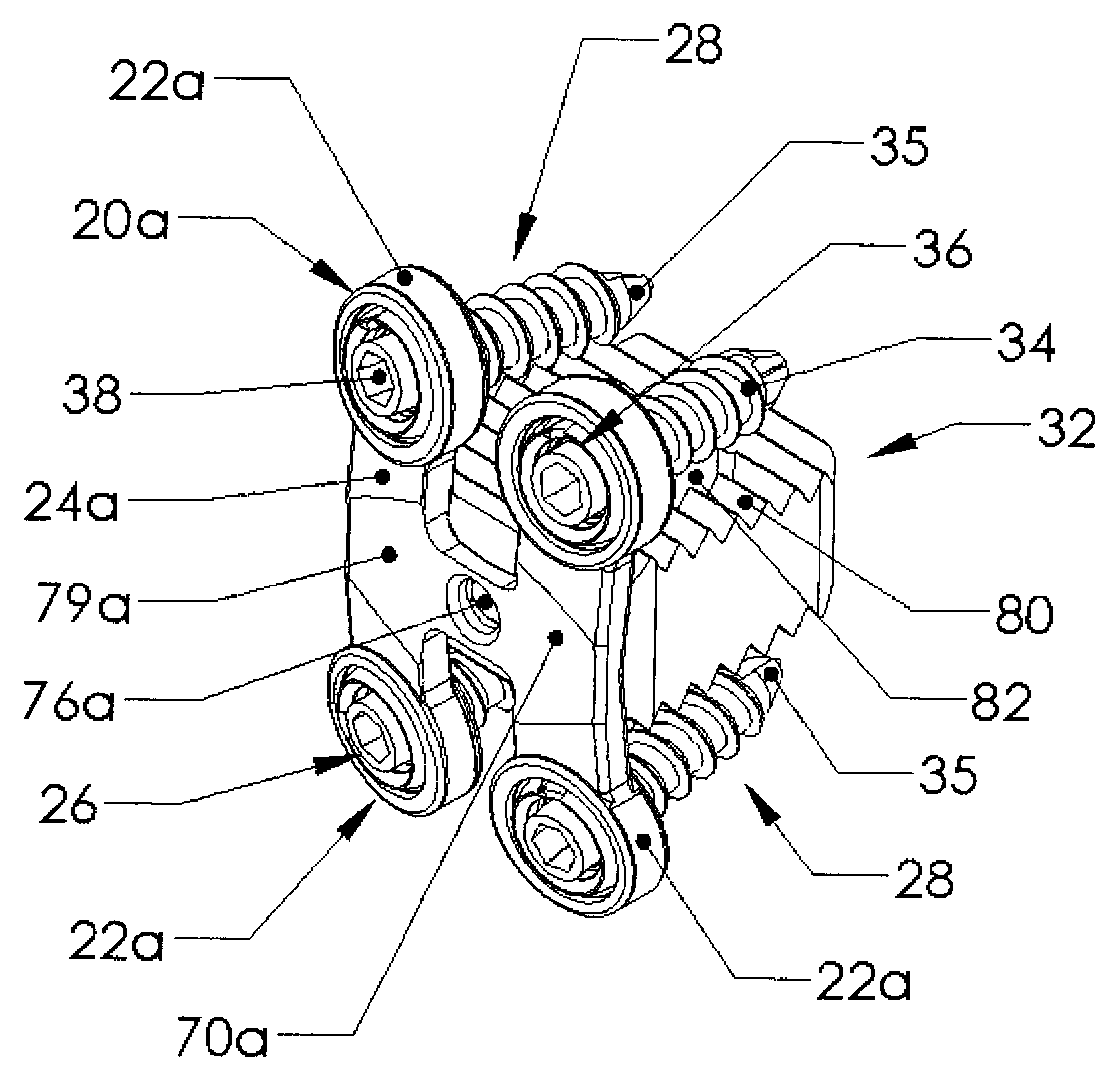
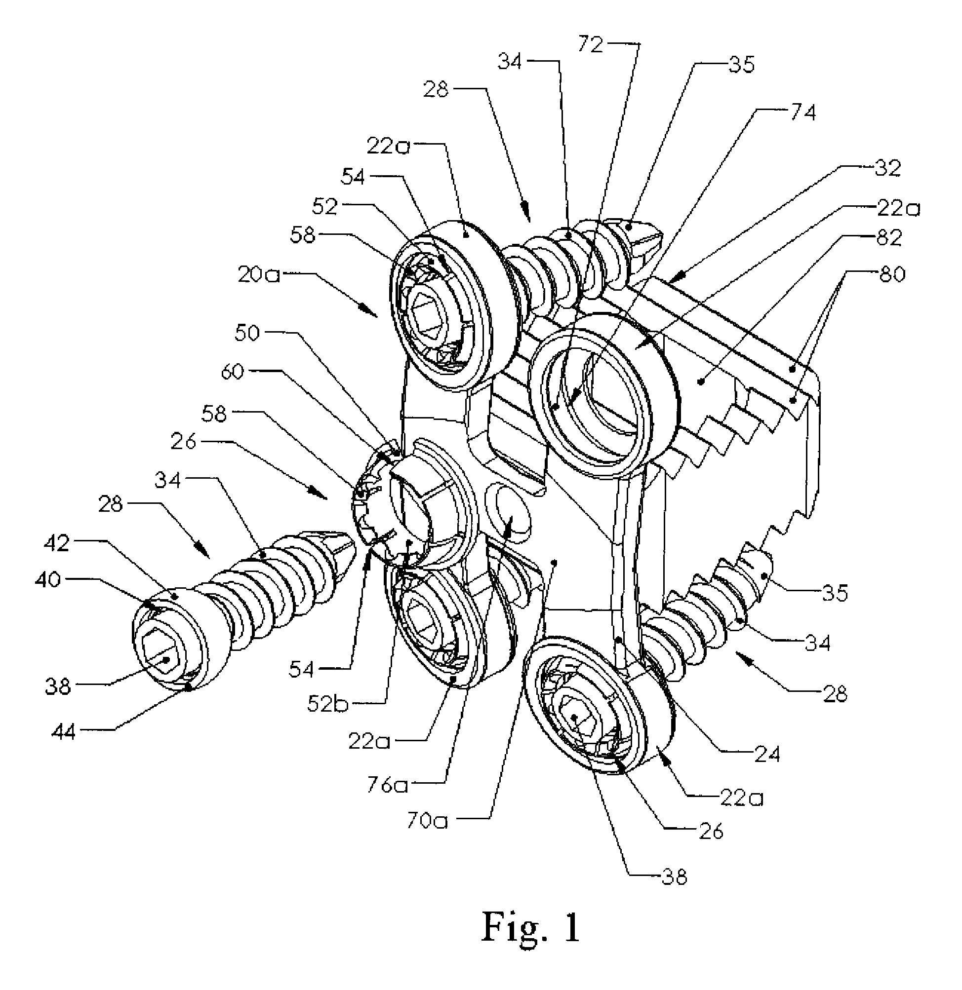
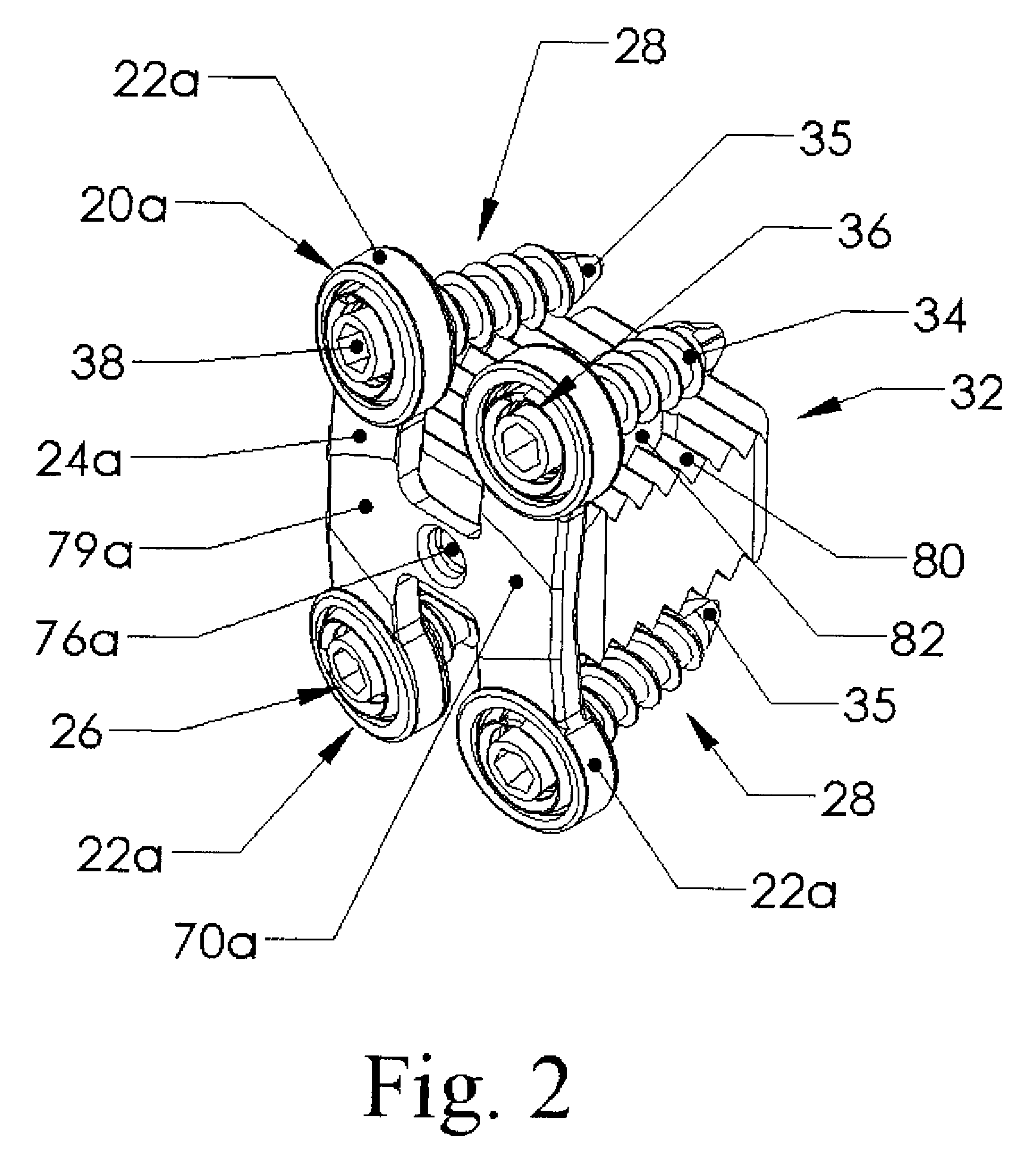
[0098]Referring to FIGS. 1-5, a bone fixation plate 20a has a generally H-shape with four sockets 22a, one at each end of the legs 24a of the H-shaped plate 20a. A bushing 26 fits within each socket 22. A bone screw 28 fits through each bushing and threads into vertebrae 30 to fasten the plate to the vertebrae 30. A vertebral body replacement 32 is fastened to the plate 20a and fits between adjacent vertebrae 30. The vertebral body replacement 32 is optional. Moreover, the fixation plate may or may not have a mount for the vertebral body replacement and may or may not have a graft attachment mount. The fixation plate 20a is believed suited for use with cervical vertebrae C2 through T1, and is believed especially suitable for C5-C6 fixation. This is referred to as a one-level fixation plate fixing two adjacent vertebrae 30 and one intervening disc.

[0099]Referring to FIGS. 1 and 6-7, the bone screw 28 is made of stainless steel, titanium or other...


PUM


Abstract

A spinal fixation assembly has a bone screw with head having a continuously curved spherical outer surface. The curved surface nests in a split annular bushing having a plurality of segments curving around the screw head. The bushing has an outward extending flange that fits into a recess in a socket in a fixation plate. The plate has at least three legs which extend from ends of a cross-member to form one of an H shaped, X shaped or A shaped configuration. Each socket is curved to rotatably receive rotation of the bushing. The socket recess is larger than the bushing flange to allow the bushing to tilt a predetermined amount depending on a thickness of the outward extending flange.

Description

BACKGROUND[0001]The present invention relates to locking fixation assemblies used in bone fixation.[0002]Neurological and orthopedic surgeons performing spine surgery use fixation plates to treat spinal disorders including spinal anomalies, spinal injuries, disc problems and bone problems to effect fusion of vertebrae. These fixation plates are typically held by one or more screws passing through the plate and into the vertebrae above and below the injured or replaced disc. During installation of the fixation plate, the screws must be allowed to be positioned by the surgeon to provide best fitted conformity to enhance fusion rates. Misalignment can lead to fracture of the screws or wear-inducted loosening in the fixation plate assembly. There is thus a need for an easily installed fixation plate that accommodates variable angles between the fixation screws and the fixation plate.[0003]Many of the current fixation plates are rigid. An unduly stiff plate can result in undue wear betwe...

Claims


Application Information

Patent Timeline
Patent Type & Authority Patents(United States)
IPC IPC(8): A61B17/56A61F2/44A61B17/80A61B17/58
CPCA61B17/7059A61B17/8047A61B17/8894A61F2/447A61B17/92A61F2002/2817A61F2002/30166A61F2002/30176A61F2002/30446A61F2002/30578A61F2002/30604A61F2002/30794A61F2002/30892A61F2002/4475A61F2002/449A61F2220/0041A61F2230/0028A61F2230/0054A61F2310/00017A61F2310/00023A61F2002/30433A61F2002/30593A61F2002/3079
Inventor ANDERSON, MARK E.MUNOZ, PAUL A.
Owner WESTMARK MEDICAL
Why Eureka
Try Eureka