Voltage converter with combined buck converter and capacitive voltage divider

a voltage converter and capacitive voltage technology, applied in the direction of electric variable regulation, process and machine control, instruments, etc., can solve the problems of reducing efficiency, reducing the output current of ac to dc adapters, and not being able to reduce efficiency

Inactive Publication Date: 2013-04-23
INTERSIL INC
View PDF70 Cites 65 Cited by
  • Summary
  • Abstract
  • Description
  • Claims
  • Application Information

AI Technical Summary

Problems solved by technology

It is difficult, however, to optimize the downstream converters used to generate the various reduced voltage levels needed in the electronic device using a 19V input voltage level.
The increased output current of the AC to DC adapter reduces efficiency.
Also, if a rechargeable battery is provided, the voltage may not be reduced below that battery voltage in order to ensure sufficient voltage to charge the battery.

Method used


Image

  • Voltage converter with combined buck converter and capacitive voltage divider
  • Voltage converter with combined buck converter and capacitive voltage divider
  • Voltage converter with combined buck converter and capacitive voltage divider

Examples


Embodiment Construction

[0011]The following description is presented to enable one of ordinary skill in the art to make and use the present invention as provided within the context of a particular application and its requirements. Various modifications to the preferred embodiment will, however, be apparent to one skilled in the art, and the general principles defined herein may be applied to other embodiments. Therefore, the present invention is not intended to be limited to the particular embodiments shown and described herein, but is to be accorded the widest scope consistent with the principles and novel features herein disclosed.

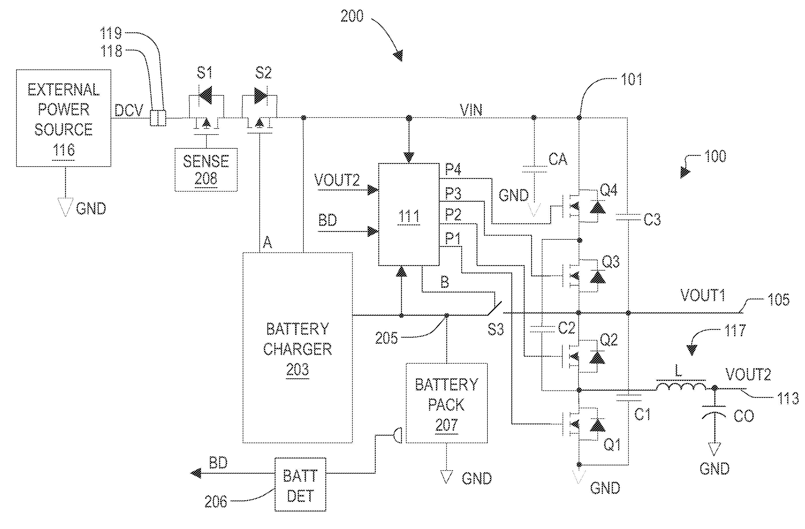
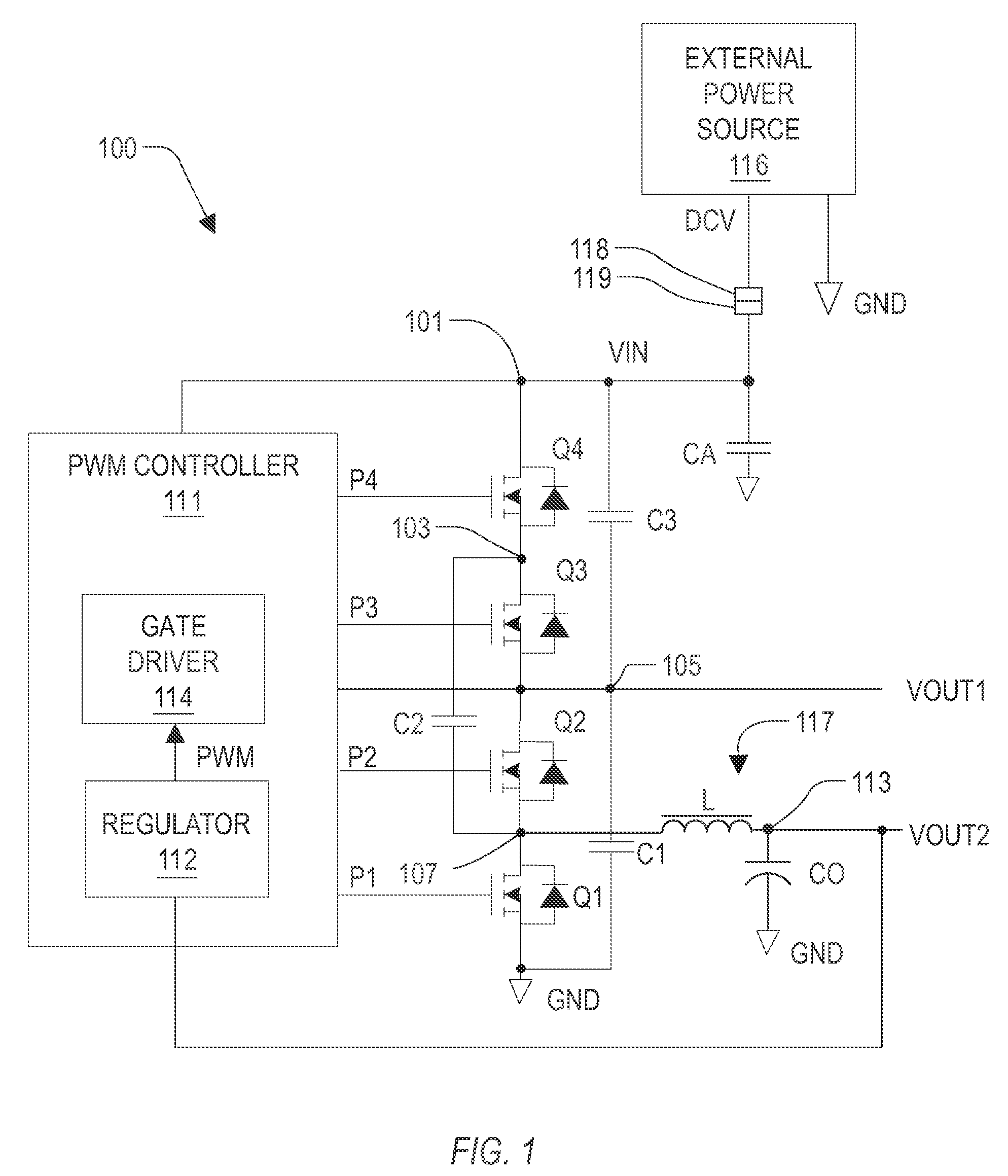
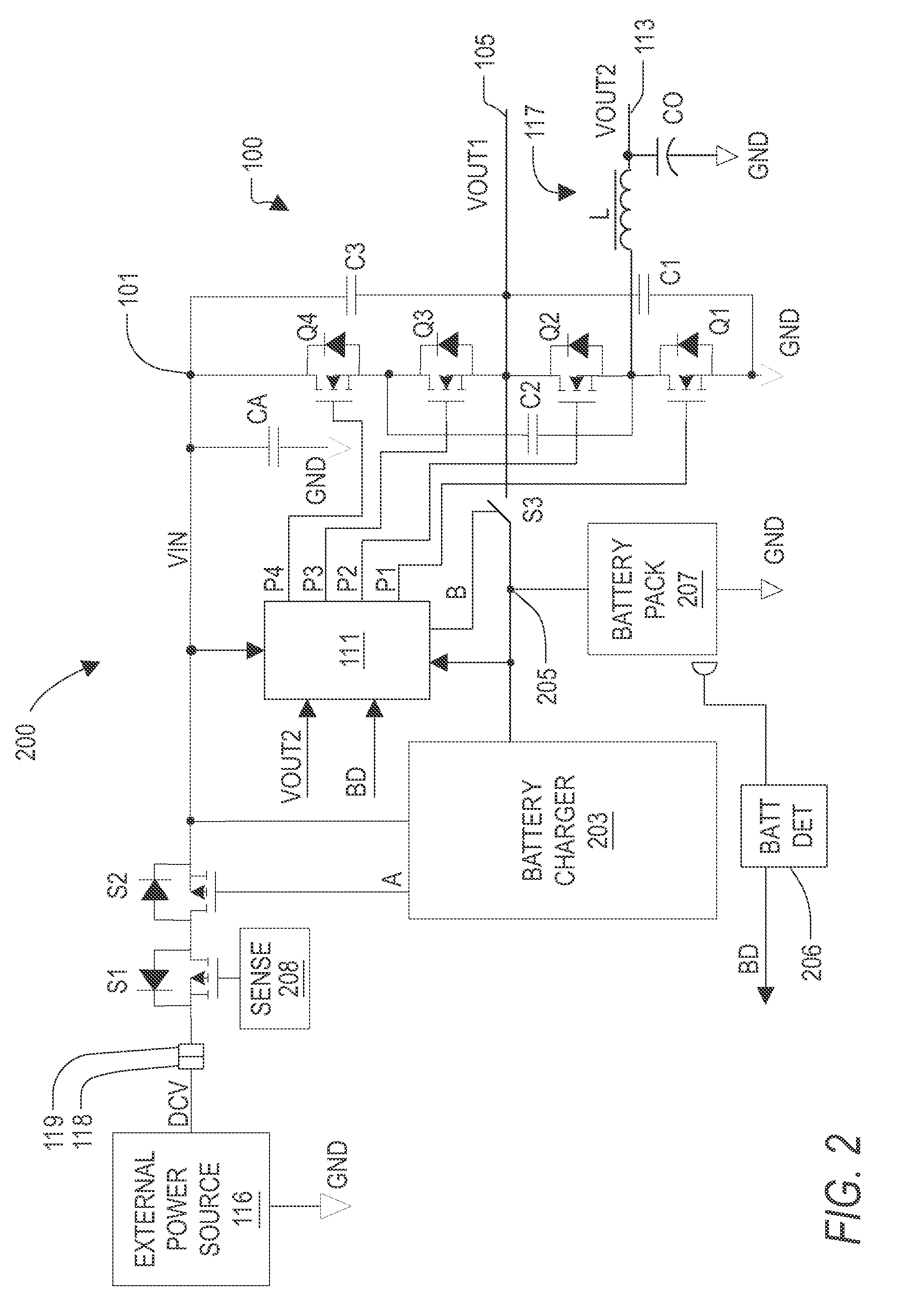
[0012]FIG. 1 is a schematic and block diagram of a voltage converter 100 with combined synchronous buck converter 117 and capacitor voltage divider according to an exemplary embodiment. The voltage converter 100 includes four electronic switches Q1, Q2, Q3 and Q4 coupled in series between an input node 101 and a reference node, such as ground (GND). In the illustrated embodimen...


PUM


Abstract

A voltage converter including a buck converter and a capacitive voltage divider. The converter includes four capacitors, a switch circuit, an inductor and a controller. A first capacitor is coupled between a reference node and a first output node which develops a first output voltage. A second capacitor is coupled between an input node and either the reference node or the first output node. The switch circuit couples a third capacitor between the reference and first output nodes in a first state of a PWM signal, and couples the third capacitor between the first output and input nodes in a second PWM signal state. The inductor is coupled to the third capacitor and provides a second output node coupled to the fourth capacitor providing a second output voltage. The controller controls the duty cycle of the PWM signal to regulate the second output voltage to a predetermined level.

Description

CROSS-REFERENCE TO RELATED APPLICATIONS[0001]This application claims the benefit of U.S. Provisional Application Ser. No. 60 / 953,254, filed on Aug. 1, 2007, which is herein incorporated by reference for all intents and purposes. This application also claims the benefit of U.S. Provisional Application Ser. No. 61 / 058,426, filed on Jun. 3, 2008, which is herein incorporated by reference for all intents and purposes. This application is also related to application entitled “VOLTAGE CONVERTER WITH COMBINED CAPACITIVE VOLTAGE DIVIDER, BUCK CONVERTER AND BATTERY CHARGER” filed concurrently herewith at least one common inventor and which is commonly assigned, which is herein incorporated by reference for all intents and purposes.DESCRIPTION OF THE RELATED ART[0002]It is often desired or advantageous to reduce an input voltage to lower voltage levels to improve efficiency of an electronic device. For example, the most commonly used AC to DC adapter for a notebook computer converts AC voltag...

Claims


Application Information

Patent Timeline
Patent Type & Authority Patents(United States)
IPC IPC(8): H02J7/04G05F1/00
CPCH02J7/0065H02M3/1588H02M3/07H02J7/0072Y02B40/90Y02B70/1466H02J2207/20Y02B70/10H02J7/00711H02J7/007182H02M7/4837H02M3/155Y02B40/00
Inventor XING, KUNMILLER, GREG J.
Owner INTERSIL INC
Why Eureka
Try Eureka